Transmission for a Vehicle

a technology for transmissions and vehicles, applied in mechanical devices, transportation and packaging, gearing, etc., can solve the problems of increasing the size of the transmission, requiring significant structural complexity, etc., and achieves low component stress, good toothing efficiency, and compact design.

Active Publication Date: 2017-03-30
ZF FRIEDRICHSHAFEN AG
View PDF0 Cites 0 Cited by
  • Summary
  • Abstract
  • Description
  • Claims
  • Application Information

AI Technical Summary

Benefits of technology

[0023]According to one exemplary embodiment, the central gear, formed as a sun gear, of the second planetary gear set is constantly connected in a torque-proof manner to that central gear, formed as a ring gear, of the first planetary gear set that meshes with the smaller effective diameter of the planetary gears. Through the connection at the smaller ring gear of the first planetary gear set, a radially compact structure of the transmission is favored. For this purpose, it is advantageous to design the central gear formed as a sun gear of the first planetary gear set, which meshes with the larger effective diameter of the planetary gears, fixable in a torque-proof manner by a first shifting element. It is further advantageous to design the central gear, formed as a sun gear, of the first planetary gear set, which meshes with the smaller effective diameter of the planetary gears, fixable in a torque-proof manner by a second shifting element. The central gear, formed as a ring gear, of the second planetary gear set is preferably to be designed fixable in a torque-proof manner by a third shifting element. Such ring gear can be connectable to the drive shaft of the transmission by locking a fourth shifting element. The central gear, formed as a ring gear, of the first planetary gear set, which meshes with the larger effective diameter of the planetary gears, is preferably connectable to the drive shaft of the transmission by a fifth shifting element. A transmission with such an allocation of the individual transmission elements features a compact design, low component stress and a good toothing efficiency.
[00

Problems solved by technology

This requires a significant structural complexity, and increases the size of the transmission c

Method used


Image

  • Transmission for a Vehicle
  • Transmission for a Vehicle
  • Transmission for a Vehicle

Examples


Embodiment Construction

[0041]Reference will now be made to embodiments of the invention, one or more examples of which are shown in the drawings. Each embodiment is provided by way of explanation of the invention, and not as a limitation of the invention. For example, features illustrated or described as part of one embodiment can be combined with another embodiment to yield still another embodiment. It is intended that the present invention include these and other modifications and variations to the embodiments described herein.

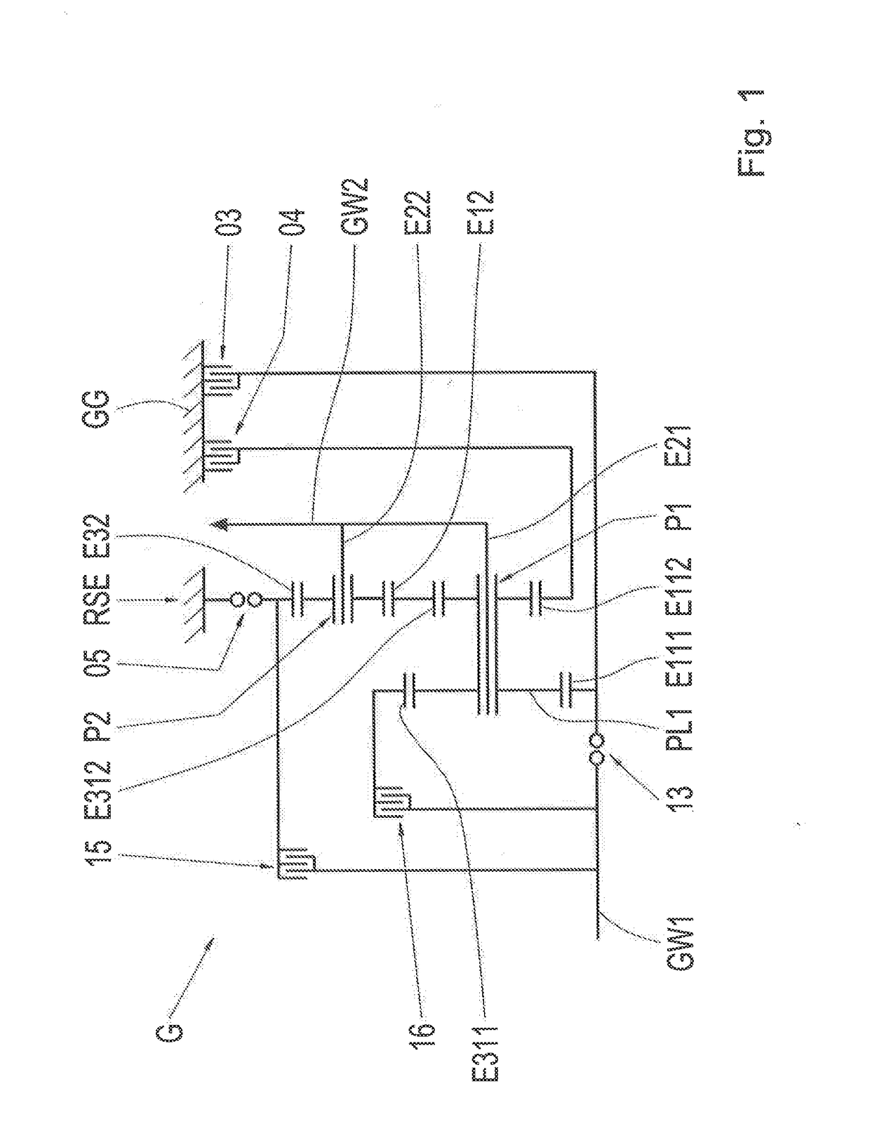
[0042]FIG. 1 schematically shows a transmission G according to a first exemplary embodiment of the invention. The transmission G features a first planetary gear set P1, which is formed as a staged planetary gear set. The transmission G also features a second planetary gear set P2, which is formed as a simple negative gear set. The first planetary gear set P1 features a total of four central gears E111, E112, E311, E312, namely the two central gears E111, E112 formed as sun gears, ...


PUM


Abstract

A transmission for a motor vehicle includes a first planetary gear set with at least three central gears which are formed by a ring gear and two sun gears or by two ring gears and one sun gear. A second planetary gear set includes two central gears which are formed by one ring gear and one sun gear. One of the central gears of the second planetary gear set is constantly connected in a torque-proof manner to one of the central gears of the first planetary gear set. The one of the central gears of the first planetary gear set differs from and is arranged in a common gear set plane with the one of the central gears of the second planetary gear set. A carrier of the first planetary gear set is constantly connected in a torque-proof manner to a carrier of the second planetary gear set.

Description

FIELD OF THE INVENTION[0001]The invention relates generally to a transmission for a motor vehicle. Herein, a transmission in particular designates a multi-speed transmission, with which a multitude of gears, thus fixed transmission ratio relationships between the drive shaft and the output shaft of the transmission, are shiftable by shifting elements, preferably automatically. Here, the shifting elements comprise, for example, clutches or brakes. Such transmissions are primarily used in automotive applications, in order to adjust the rotational speed and torque output characteristics of the drive unit to the driving resistance of the vehicle in a suitable manner.BACKGROUND[0002]Patent application DE 31 31 138 A1 of the applicant describes a load-shiftable planetary gear change-speed transmission with several coupled planetary gear sets. Therein, a staged planetary gear set is used, on the carrier of which planetary gears with different effective diameters are arranged. In the embodi...

Claims


Application Information

Patent Timeline
IPC IPC(8): F16H3/66
CPCF16H3/66F16H2003/442F16H2200/0052F16H2200/0086Y10S903/919F16H2200/2046F16H3/724B60K6/365B60Y2300/70F16H2200/2007B60K6/48B60K2006/4825F16H2200/201F16H2200/2064F16H2200/2094Y02T10/62
Inventor BECK, STEFANWARTH, VIKTORWECHS, MICHAELBREHMER, MARTIN
Owner ZF FRIEDRICHSHAFEN AG
Why Eureka
Try Eureka