[0006]Since
energy demand is responsive to output error, which error remains uncorrected without energy balance, an energy demand
signal tends to be self-preserving from cycle to cycle, even if partial error correction has occurred. In most
converters, some sort of ramp more or less accurately represents
energy supply. If this ramp be reset for each chopping cycle, whilst an
inductor continues to charge from a given cycle to a later cycle, this ramp will grossly misrepresent energy supply. If, however, inductive current, or a
volt-time representation thereof, is incorporated into the energy supply term, energy supply information survives from cycle to cycle allowing inductive energy supply to be controlled to match energy demand over multiple cycles. By thusly controlling a switched-mode
buck power converter with
energy balancing, its main
feedback loop may be kept closed even when balance of energy demand and energy supply is not attained within a single chopping cycle. Such multi-cycle balance control optimizes
transient response and stability. It should be noted that a substantially accurate estimate of
inductor pedestal, or valley, current is needed to maintain energy balance in a converter operating in the CCM. Linear and squared control terms are piecewise-proportional when those terms remain close to unity. Accordingly, the advantages of
energy balancing in a
buck converter are limited until the converter becomes significantly out of energy balance. For that reason, this invention also teaches multi-cycle energy balancing buck converter control based on
voltage and time, as a
volt time product can approximate energy.
[0007]Partial implementations of this invention, squaring neither demand nor supply terms, or squaring but one of the two, are possible. Note that most partial implementation would only make sense in a parts-constrained analog environment. With a digital controller, there would be little reason to forgo the improvement provided by squared terms. As more energy terms are represented by squares, (combined with appropriate
gain corrections) dynamic performance improves. Because inductive current varies over the widest range, it is the most important term to square, be it a time term, a
volt-time product, or a measured current. Note that an AC coupled inductive current term can be sufficient, since time alone is adequate for determining the supply term under static conditions. The inductive current signal is only needed to correct for energy stored in the inductor during rapidly changing conditions, or across multiple cycles. Another utile partial implementation would practice conventional control for steady-state operation, but switch to energy balancing control if regulation was lost.
[0008]Control loops according to this invention not only work over a range of duty cycles from under 1% to over 80%, but can also remain stable over multiple control cycles. Predictive energy balancing control can also lower component stresses to improve reliability by minimizing unnecessary swings in inductor current and undesired swings in output voltage.
[0009]Under any one set of operating conditions, converters practicing prior-art control can be made stable through compensation techniques and appropriate
gain settings. The circuits and methods taught here allow stable operation over a wider range of conditions. Component's resistance,
capacitance and
inductance change with time and temperature, and load
capacitance and current can change unpredictably, so flexibility brings benefits even under constrained conditions. Also, more responsive control allows more aggressive digital
power management strategies. The ability to maintain stable operation over a wider range of conditions improves utility and reliability.
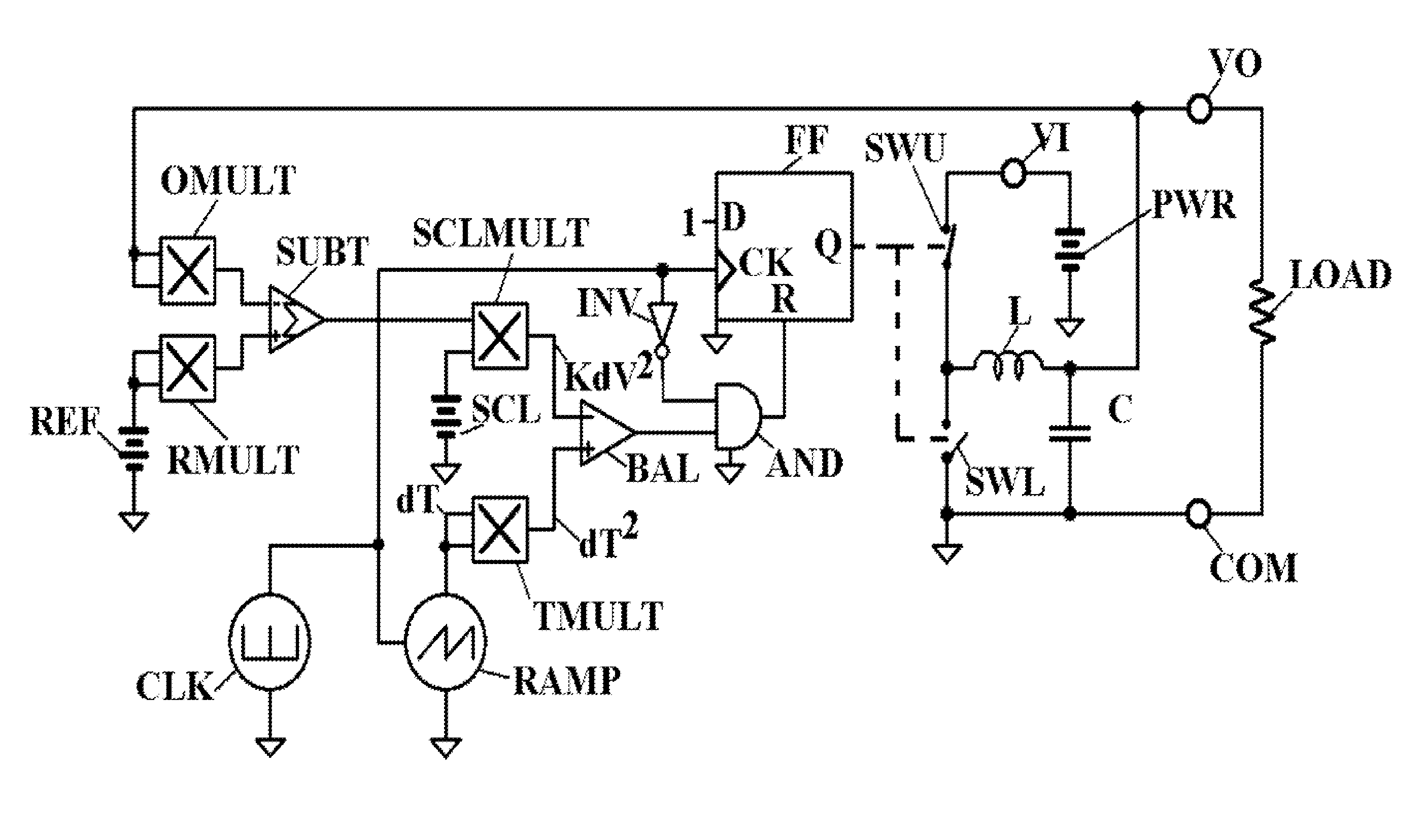
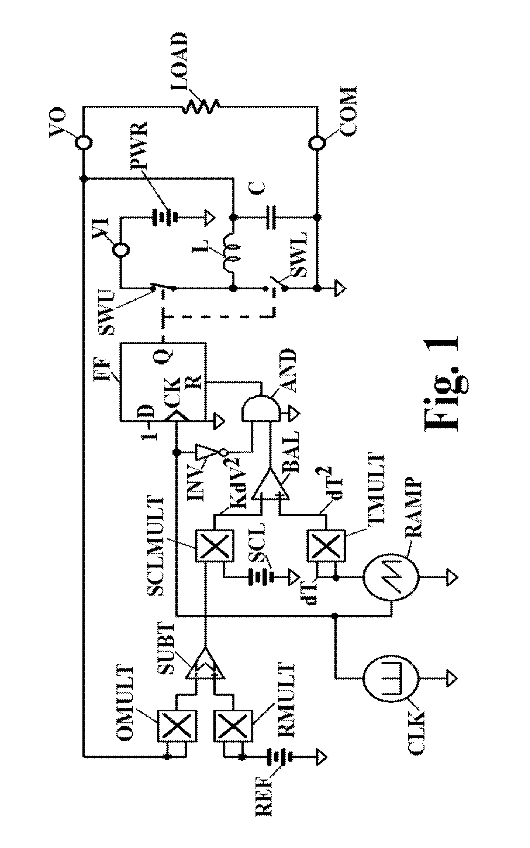
[0013]When this converter is operated in the
continuous current mode (CCM), stability and
transient response may be improved by adding inductive current pedestal control according to this invention. It is well-known that the duty-cycle of a lossless buck converter is equal to output voltage divided by input voltage. Thus, the time of
inductive charging equals the product of cycle period and desired voltage divided by input voltage. For a loss-less converter, such
time control alone of a switch controlling an inductor might provide correct average output voltage, albeit with perhaps unacceptable transient behavior. Real converters, however, require closed feedback loops to improve transient behavior and to accommodate losses. The portion of the invention described above provides regulation and superior transient response in the discontinuous
current mode (DCM), but may be improved according to this invention, as shown below, when the converter is operated in the CCM.
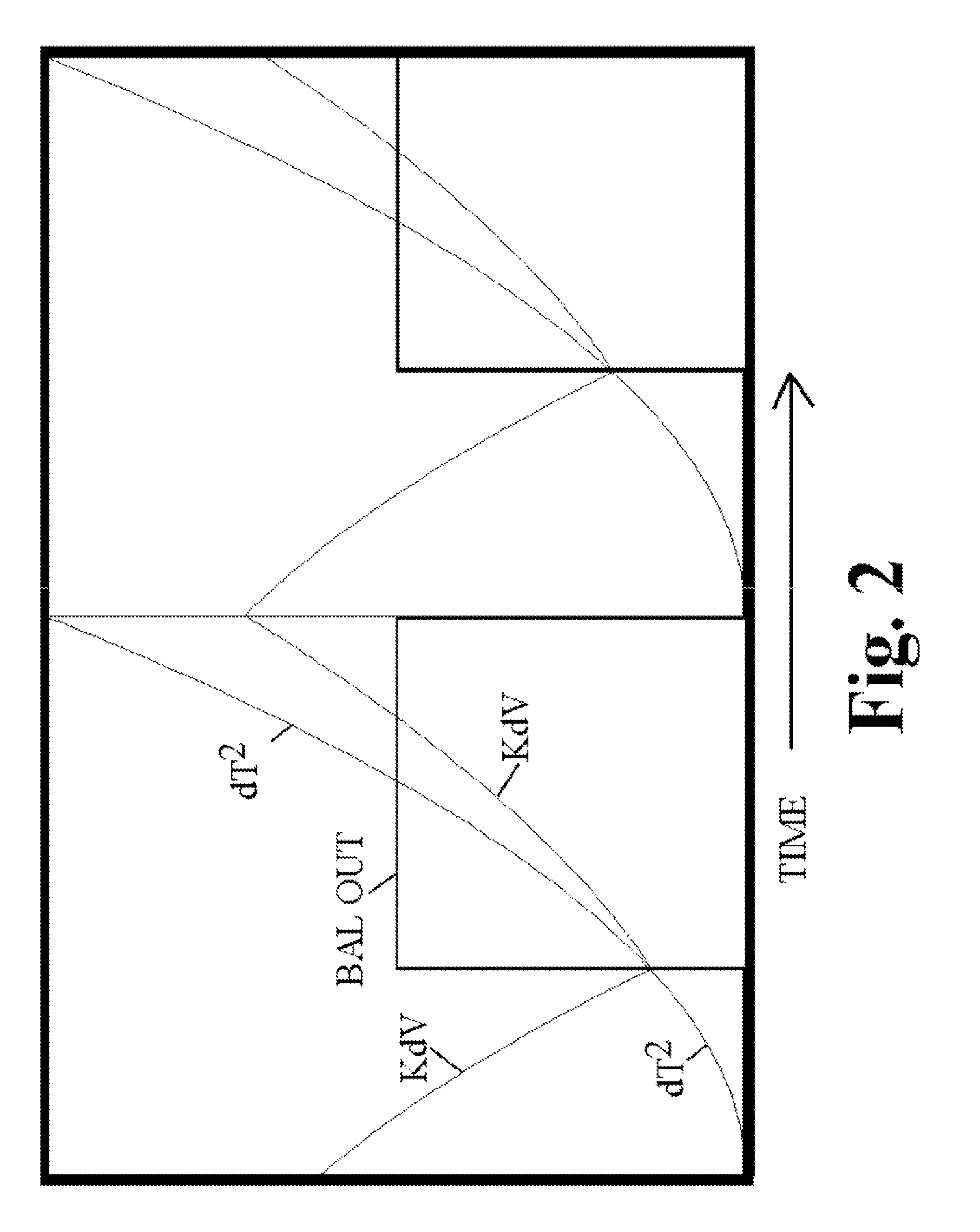
[0017]Therefore if the pedestal of that cycle has been too low or too high, it is too late to add or refrain from adding inductive energy during that cycle. Correction must then be made, in accordance with the prior art, in subsequent cycles, which invites sub-
harmonic ripple generation and inferior transient response. Correction according to this invention predicts whether the inchoate inductive current pedestal will match energy demand. If either under-supply or over-supply is predicted, this pedestal control adjusts inductive reactor charging time immediately to control inductive energy, without waiting for output voltage to drop or rise. Thus transient
load regulation is improved and sub-
harmonic ripple generation is reduced.

