
Pipe Fitting With Sensor

a technology of pipe fittings and sensors, applied in the field of pipe fittings, can solve the problems of not offering continuing information about the state of the pipe fitting over its useful life, harsh and sour, and testing is typically only useful

Active Publication Date: 2017-03-30
LENLOK HLDG LLC
View PDF5 Cites 46 Cited by
  • Summary
  • Abstract
  • Description
  • Claims
  • Application Information

AI Technical Summary

Benefits of technology

The patent describes a fluid fitting that can be attached to a pipe using a mechanical joint. The fitting includes a main seal and a ring that compress the seal to create a tight connection. The attachment also includes an electrically operated sensor device that produces a signal when the fitting moves. The sensor can be integrated into the mechanism of the fitting, making it easy to attach and monitor. The invention allows for quick and easy attachment of fluid fittings to pipes, with minimal risk of leaks or damage.

Problems solved by technology

However, these types of tests are typically only useful at the actual time of installation, and may only provide indirect evidence that the fitting is properly installed upon the pipe.
Moreover, these tests in particular do not offer continuing information about the state of the fitting over its useful lifetime.
Often, these fluid fittings are used in harsh and sour environments in the presence of corrosive process fluids or gases, such as Hydrogen Sulfide.
For example, H2S in the presence of water can result in damage to carbon steel pipelines in the form of corrosion, cracking, or blistering.
The effects of H2S on steel can result in sulphide stress cracking (SSC), hydrogen induced cracking (HIC), and corrosion.
The presence of carbon dioxide in the sour environment tends to increase the corrosion rate in the steel.
These effects can jeopardize the fluid fitting and pipe.

Method used


Image

  • Pipe Fitting With Sensor
  • Pipe Fitting With Sensor
  • Pipe Fitting With Sensor

Examples


Embodiment Construction

[0017]Example embodiments are described and illustrated in the drawings. These illustrated examples are not intended to be a limitation on the present invention. For example, one or more aspects can be utilized in other embodiments and even other types of devices. Moreover, certain terminology is used herein for convenience only and is not to be taken as a limitation. Still further, in the drawings, the same reference numerals are employed for designating the same elements.

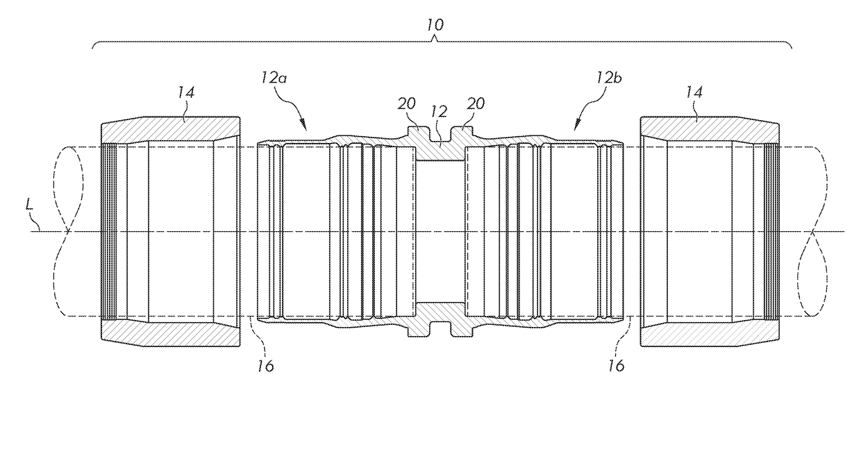
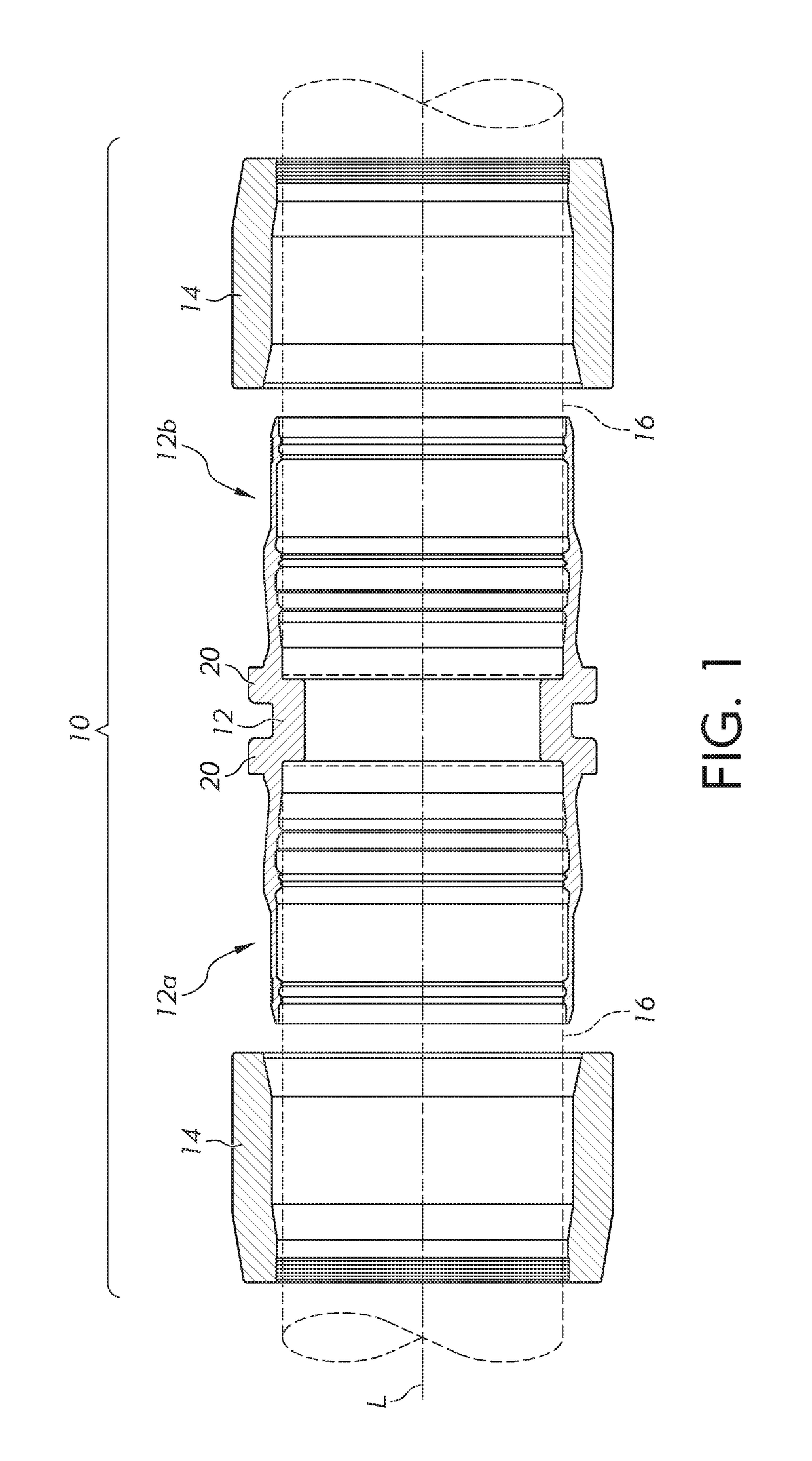
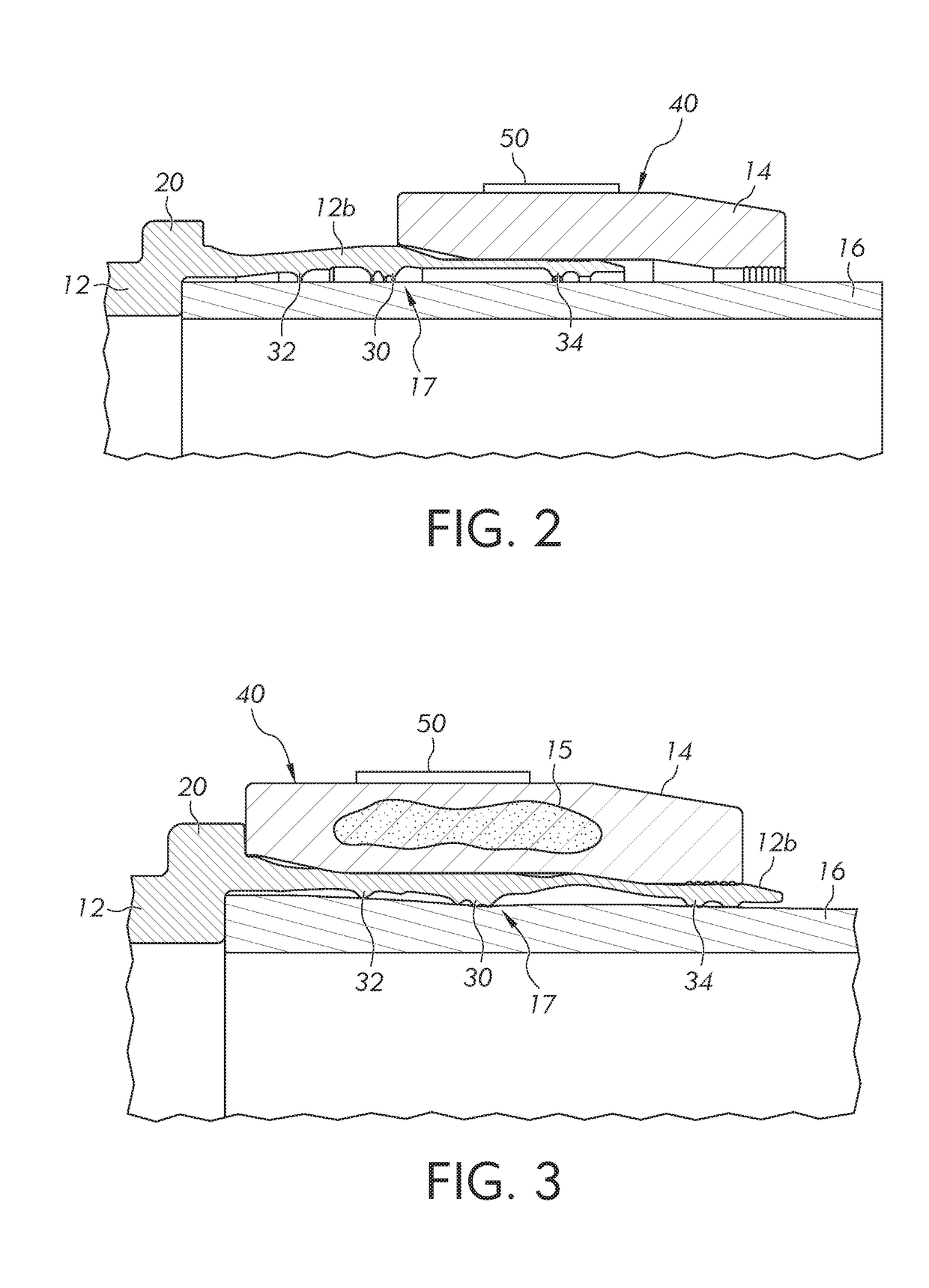
[0018]Turning to the shown example of FIG. 1, the example fitting 10 may be utilized to connect either thin walled or thick walled pipes, such as those ranging in size from ¼″ NPS to 4″ NPS, although other pipe sizes may also derive a benefit from the example fitting 10. The example fitting 10 includes predetermined ratios of interference between a drive ring 14 (sometimes referred to as a “swage ring”), body 12, and pipe 16 along the length of a cylindrical contact area. The example fitting 10 may be installed on...


PUM

PropertyMeasurementUnit
compressive forceaaaaaaaaaa
elastic deformationaaaaaaaaaa
electrical parameteraaaaaaaaaa

Abstract

A fluid fitting is provided that is mechanically attached to a pipe, including a coupling body having an inner surface defining a bore for receiving the pipe therein. A ring is positioned to fit over the at least one end of the coupling body for mechanically attaching the coupling body to the pipe, and a main seal formed on the inner surface of the coupling body to engage the pipe. When installed, the ring and coupling body apply a compressive force to the main seal sufficient to attach the pipe to the coupling body in a non-leaking manner. An electrically operated sensor device is fixed to a surface of one of the coupling body or ring that, when the ring is installed on the coupling body, produces an electrical parameter in response to physical movement of the coupling body or ring to which the sensor device is fixed.

Description

CROSS-REFERENCE TO RELATED APPLICATIONS[0001]This application claims the benefit of U.S. Provisional Application No. 62 / 251,853, filed Nov. 6, 2015 and U.S. Provisional Application No. 62 / 232,017, filed Sep. 24, 2015, the entire disclosures of which are hereby incorporated herein by reference.FIELD OF THE INVENTION[0002]The present invention relates generally to a fluid fitting for mechanically attaching and sealing a pipe, and more particularly, to a wireless sensor attached to the fluid fitting and method of use.BACKGROUND OF THE INVENTION[0003]Generally, one type of fitting for fluid conduits, such as tubes or pipes, includes a connector body that fits loosely over the fluid conduit and a drive ring which compresses and / or physically deforms the connector body against the outside surface of the fluid conduit to provide one or more seals and to provide a strong mechanical connection.[0004]Conventionally, various physical inspection tests have been developed to confirm a proper ins...

Claims


Application Information

Patent Timeline
Patent Type & Authority Applications(United States)
IPC IPC(8): F16L15/08F16L15/00
CPCF16L15/08F16L2201/10F16L15/006F16L15/009F16L13/146G01M5/0025G01M5/0033G01M5/0083F16L21/007F16L21/04F16L25/12F16L55/00F17D5/00F16L21/00Y10T29/49908
Inventor LENNON, WILLIAM H.
Owner LENLOK HLDG LLC
Learn More