Port Connection for a Heat Exchanger

a heat exchanger and port connection technology, applied in indirect heat exchangers, laminated elements, lighting and heating apparatus, etc., can solve the problems of increasing the cost of installation, and increasing the cost of port connection, so as to reduce the cost and time of installation.

Inactive Publication Date: 2017-03-30
SPX FLOW INC
View PDF5 Cites 2 Cited by
  • Summary
  • Abstract
  • Description
  • Claims
  • Application Information

AI Technical Summary

Benefits of technology

[0006]Embodiments of the present disclosure are capable of reducing the expense...

Problems solved by technology

Unfortunately, these conventional port connects suffer from a number of shortcomings For example, elastomeric port connections are less resistant to heat and degrade relatively faster than the life of the plate heat ...

Method used


Image

  • Port Connection for a Heat Exchanger
  • Port Connection for a Heat Exchanger
  • Port Connection for a Heat Exchanger

Examples


Embodiment Construction

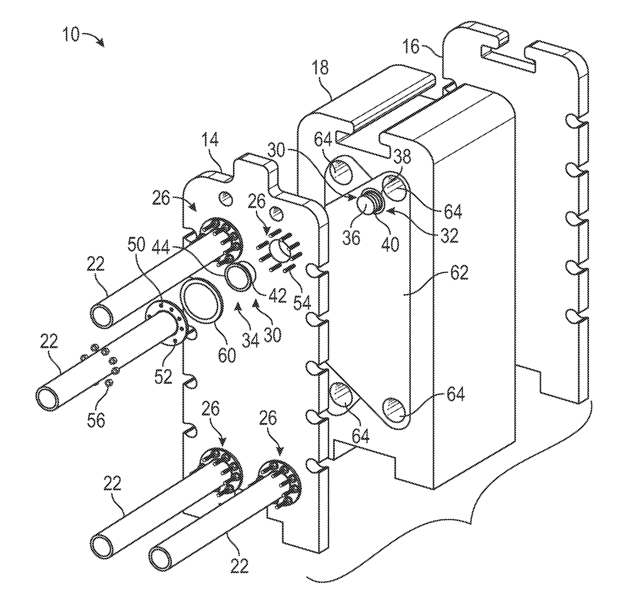
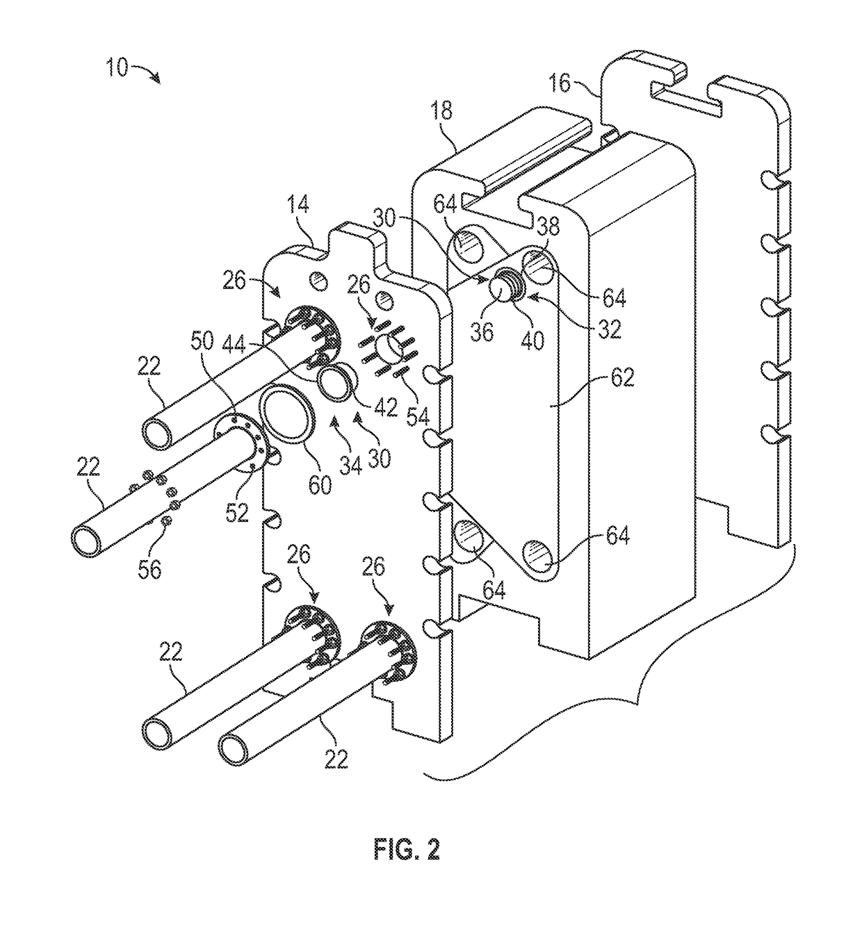
[0019]In general, embodiments of the invention pertain to a port connection for a heat exchanger that is easier to install and / or maintain than conventional port connections and / or offers cost savings over conventional port connections and a method of assembling the improved port connection in port of a pressure plate of the heat exchanger. In addition to ease of installation, improved maintenance, and reduced cost of the improved port connection described herein, tooling and machine costs are reduced by omitting welding and / or hydroforming associated with conventional port connection installation.

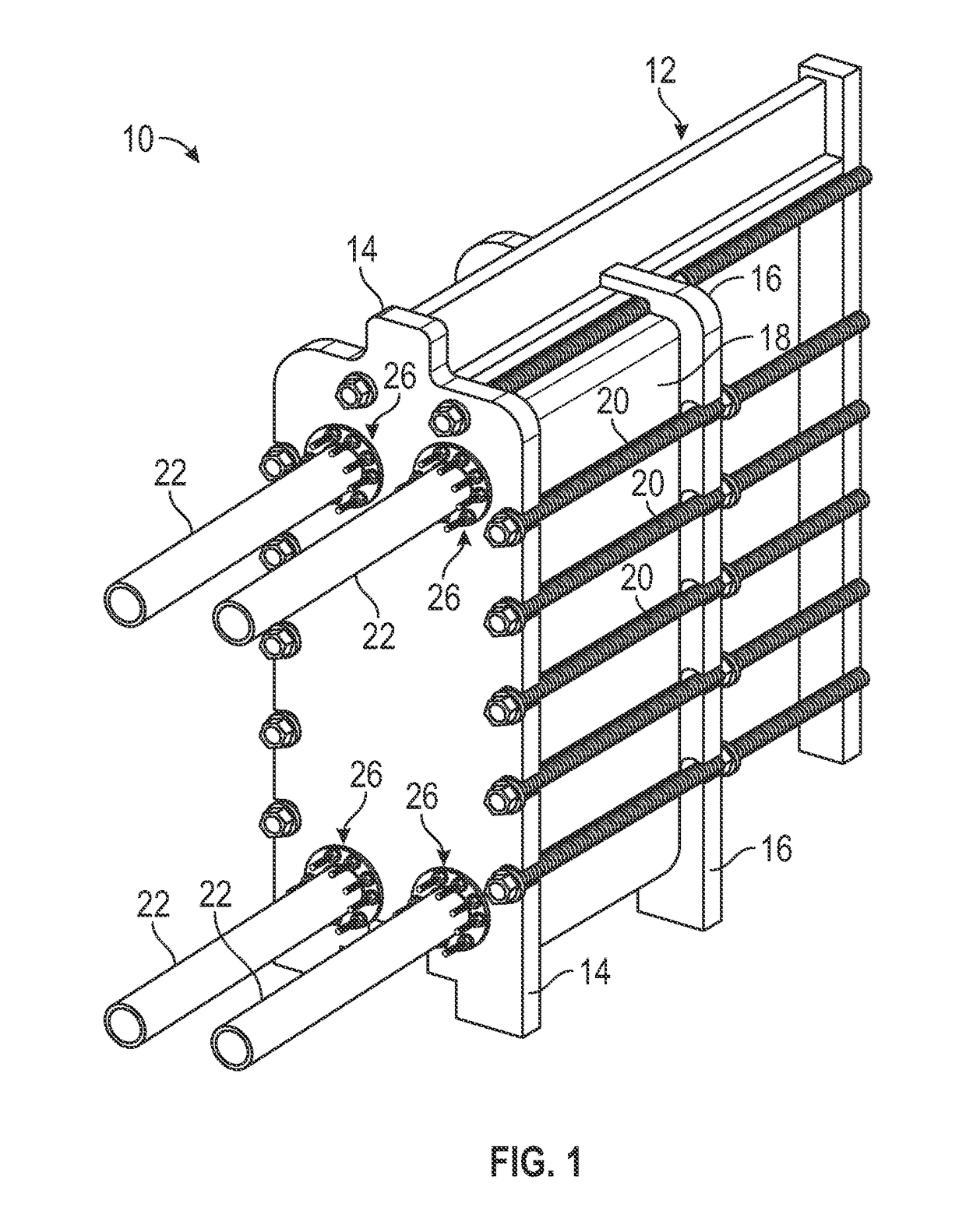
[0020]Referring now to the figures wherein like reference numerals indicate like elements, in FIG. 1 is a perspective view of a heat exchanger 10 suitable for use with embodiment of the invention. As shown in FIG. 1, the heat exchanger 10 includes a frame 12 having a pair of pressure plates 14 and 16, a plate pack 18, a plurality of tie bar assemblies 20 and a plurality of supply / output co...


PUM


Abstract

A port connection includes a first element, a second element, and a seal. The first element has a first sleeve and a first flange. The first sleeve is configured to slide into a port disposed through a pressure plate of the plate heat exchanger and the first flange having a first bearing surface to bear upon a first face of the pressure plate. The second element has a second sleeve and a second flange. The second sleeve is configured to slide into the port and the second flange having a second bearing surface to bear upon a second face of the pressure plate. The seal is generated in response to the first sleeve telescoping into the second sleeve.

Description

FIELD OF THE INVENTION[0001]The present invention relates generally to a plate heat exchanger. More particularly, the present invention relates to a port connection for use on a plate heat exchanger.BACKGROUND OF THE INVENTION[0002]Plate heat exchangers offer efficient transfer of heat from one fluid to another in a relatively small volume. Heat exchangers are typically assembled from a multitude of individual or welded pairs of plates called a plate pack that are sealed around an outer edge with a gasket material. The plate pack is compressed in a frame of the heat exchanger in order to form the seal between the plates or plate pairs. The plate pack includes inlets and outlets for the two fluids.[0003]The compression is applied uniformly across the surface of the plate pack in order to prevent leakage from the seal and reduce damage to the plates. Because of the size of the plate pack and the amount of pressure applied, the plate pack is sandwiched between two pressure plates calle...

Claims


Application Information

Patent Timeline
IPC IPC(8): F28D9/00F16L23/18
CPCF16L23/18F28D9/0093F16L41/00F16L41/12F16L41/14F28F3/08F28F3/10F28F5/00F28F9/04F28F9/12F16L41/086F28F2275/20F28F2280/06F28F2275/205F28F3/083F28F9/0246F28F9/0256F28D9/005F28F9/0248
Inventor PETERSEN, JES HANSEN
Owner SPX FLOW INC
Why Eureka
Try Eureka