Sub-surface irrigation system

a technology of irrigation system and surface area, which is applied in the field of surface area irrigation system, can solve the problems of not preventing water from escaping upwards, complicated and expensive systems, and often more expensive installation and/or maintenan

Active Publication Date: 2017-04-06
CAPILLARY CONCRETE LLC
View PDF3 Cites 7 Cited by
  • Summary
  • Abstract
  • Description
  • Claims
  • Application Information

AI Technical Summary

Benefits of technology

[0009]It is therefore an object of the present invention to provide an irrigation system and a method for providing a sub-surface irrigation system, which alleviates all or at least some of the above-discussed drawbacks of the presently known systems.

Problems solved by technology

When it comes to maximizing water efficiency one can generally say that sub-surface irrigation systems are preferable over surface irrigation systems (e.g. sprinklers, level basins, etc.), they are however often more expensive to install and / or maintain.
However, systems like these are often very complicated and costly, and furthermore pose great challenges when trying to achieve a completely uniform spread of water across a large area.
Moreover, they often require significant lengths of pipes or tubes which may be troublesome when it comes to maintenance and repairs.
The first layer will not prevent water to escape upwards, e.g. due to evaporation, however technicalities like these are assumed to be obvious for the skilled artisan.
Consequently, the risk for water accumulation on the surface of the planted area is decreased, which may be very inconvenient if the planted area is e.g. a sports area.
In these situations / locations the capillary forces might not be strong enough to overcome the gravitational force and to transport water to all parts of the porous layer, for example if the surface that the recess into which the porous layer is to be positioned has an uneven surface with protrusions / crests.

Method used


Image

  • Sub-surface irrigation system
  • Sub-surface irrigation system
  • Sub-surface irrigation system

Examples


Embodiment Construction

[0051]In the following detailed description, preferred embodiments of the present invention will be described. However, it is to be understood that features of the different embodiments are exchangeable between the embodiments and may be combined in different ways, unless anything else is specifically indicated. Even though in the following description, numerous specific details are set forth to provide a more thorough understanding of the present invention, it will be apparent to one skilled in the art that the present invention may be practiced without these specific details. In other instances, well known constructions or functions are not described in detail, so as not to obscure the present invention.

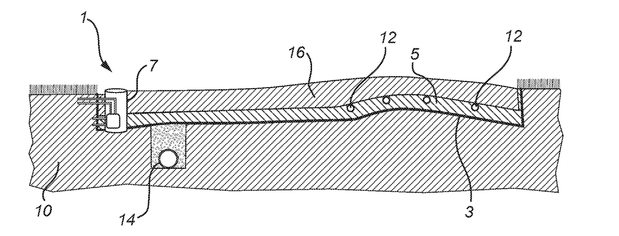
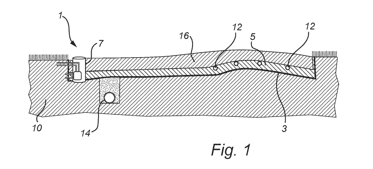
[0052]In FIG. 1, a schematic illustration of an irrigation system 1, installed in a recess or excavation in a surface area, such as e.g. a golf-green or a lawn. The irrigation system comprises a substantially water impermeable layer 3, such as e.g. a plastic sheet, rubber sheet or ...


PUM


Abstract

A system for controlling a moisture content below a surface area, where the system is installable in a recess above which the surface area will be located. The system comprises a substantially water impermeable first layer, a porous second layer and a water control basin which comprises means for controlling a moisture level of the porous second layer. The system enables liquid from the water control basin to be transported through the second layer by utilization of capillary forces, providing for an efficient sub-surface irrigation system which is easy to maintain. A method for providing such an irrigation system is also disclosed.

Description

FIELD OF THE INVENTION[0001]The present invention relates to an irrigation system for a surface area. More specifically the present invention relates to a system for controlling irrigation of a surface area by utilization of capillary forces.BACKGROUND OF THE INVENTION[0002]Irrigation systems and irrigation methods have been under constant development for thousands of years, efficient water management has many times been an overall goal when new systems and methods have been introduced. The introduction of diesel and electric motors has enabled many new concepts when it comes to irrigation (or watering) of planted surfaces and advancements in terms of reduction in manual labor and costs have been made. There is a constantly growing need for better irrigation systems and irrigation methods in order to maximize water use efficiency, i.e. supplying each plant with the amount of water it needs, no more and no less, and at the same time minimizing water losses, e.g. due to evaporation.[0...

Claims


Application Information

Patent Timeline
Patent Type & Authority Applications(United States)
IPC IPC(8): A01G25/16A01G25/06A01G25/02A01G1/00
CPCA01G25/167A01G25/023A01G25/06A01G1/001A01G2025/003A01G22/00A01G24/10
Inventor STERNBERG, MARTIN
Owner CAPILLARY CONCRETE LLC
Why Eureka
Try Eureka