Flexible container liner wringing device

a flexible container and liner technology, applied in the field of flexible container liner wringing device, can solve the problems of blocking the evacuation path, unable to completely or near-completely evacuate the contents from within the liner, and large quantities of content remaining within the liner

Active Publication Date: 2017-04-06
ILC DOVER LP
View PDF8 Cites 13 Cited by
  • Summary
  • Abstract
  • Description
  • Claims
  • Application Information

AI Technical Summary

Problems solved by technology

A problem long associated with the use of such liners has been the complete or near-complete evacuation of the contents from within the liner.
While these devices have aided in the evacuation of the liner they can still result in rather large quantities of content remaining within the liner.

Method used


Image

  • Flexible container liner wringing device
  • Flexible container liner wringing device
  • Flexible container liner wringing device

Examples


Embodiment Construction

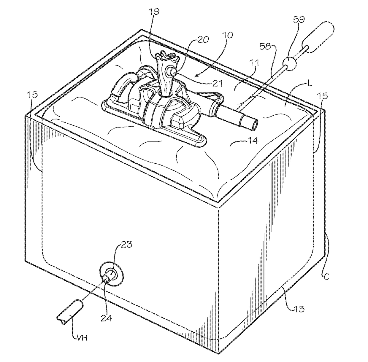
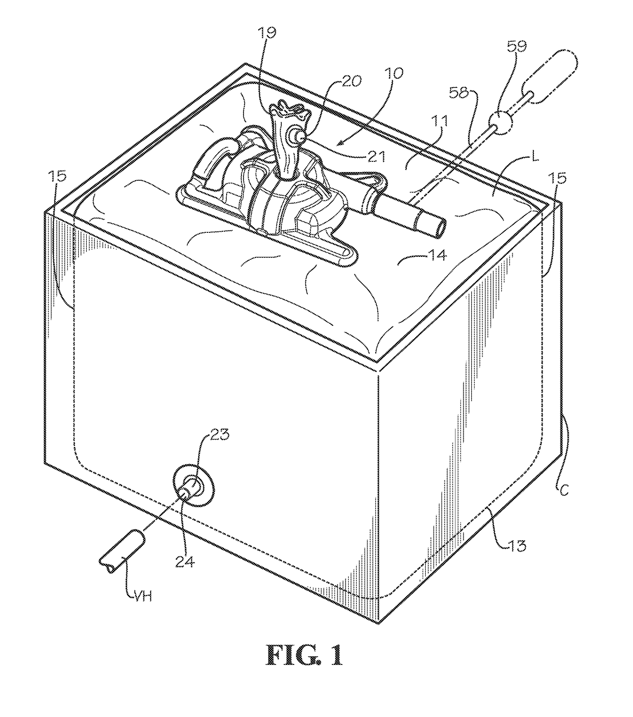
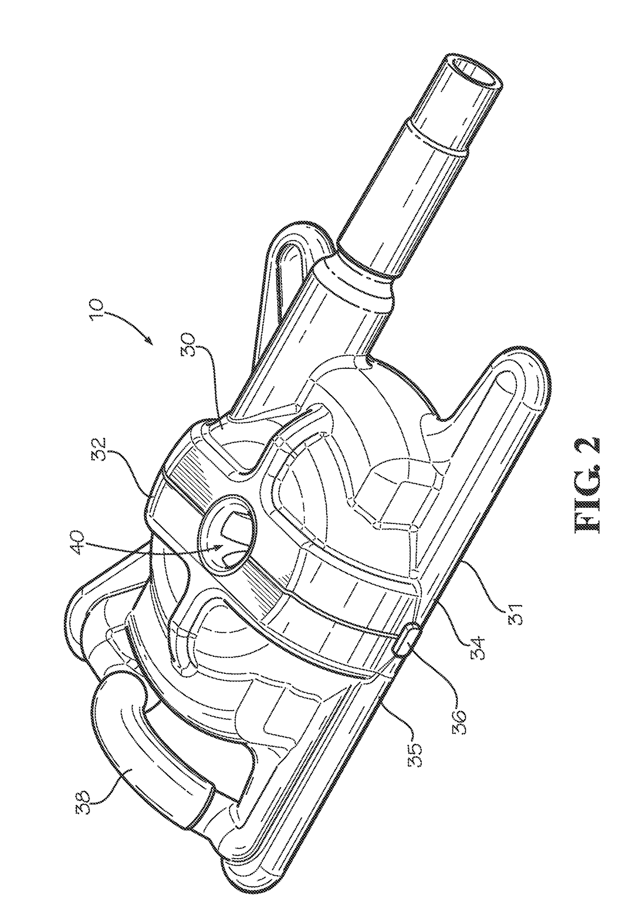
[0012]With reference next to the drawings, there is shown a flexible container liner wringing device 10 embodying principles of the invention in a preferred form. The wringing device 10 is configured to be used in conjunction with a flexible container or liner L positioned within a container C, which is preferably in the form of a rigid intermediate bulk container but which may also be in the form of a flexible bag or a semi-rigid container.

[0013]The liner L has a liner body 11 with a bottom wall 13, a top wall 14 and four peripheral side walls 15 extending between the bottom wall and top wall so as to define a generally box shape configuration. The top wall 14 also includes a tubular excess liner material or chute 19 which includes a filling fitment 20 with a fitment cap 21. The liner L also has a cylindrical, hose content inlet / outlet port or bottom fitment 23, having a fitment cap 24, which extends through the liner bottom wall 13 or side wall 15 adjacent the bottom wall. A vacuu...


PUM


Abstract

A liner wringing device (10) is disclosed for use with a container liner. The wringing device includes a housing (30) with an internal cavity which houses the mechanical components of the wringing device. The housing defines a central liner compression channel (40). The internal components include a bottom support plate (42) with a central opening 43 aligned along the central channel. The wringing device also includes a drive assembly (44) formed by four elastomeric rollers (45) positioned so that the peripheral contact surfaces (50) are aligned generally tangentially with the central channel. The four rollers are each mounted to a drive shaft/axle which includes bevel gears which are meshed so that all four rollers rotate in simultaneous, synchronic rotation through the actuation of a pneumatic air gear motor (57).

Description

TECHNICAL FIELD[0001]This invention relates to devices used to extract the material contents from liners used in conjunction with containers, and particularly to devices used to help extract the material contents from intermediate bulk container liners through the wringing of the liner.BACKGROUND OF THE INVENTION[0002]Flexible liners are oftentimes utilized in conjunction with an intermediate bulk containers which are typically 42 to inches is length, width and height, to ship large quantities of liquid, viscous or granular products. A problem long associated with the use of such liners has been the complete or near-complete evacuation of the contents from within the liner. As such, some liners have utilized pressurized regions to lift or angle the bottom of the liner or to move the interior sidewalls inwardly so as to move the contents closer to the outlet of the liner. While these devices have aided in the evacuation of the liner they can still result in rather large quantities of...

Claims


Application Information

Patent Timeline
IPC IPC(8): B65D88/54B65D90/04B30B9/20
CPCB65D88/546B65D90/046B30B9/20B65D88/54B65D2590/046B65B69/0091
Inventor SULLINGER, RANDY R.MCKEE, TONY R.
Owner ILC DOVER LP
Why Eureka
Try Eureka