Boiler control

a boiler and control technology, applied in the field of temperature control units, to achieve the effect of superior boiler control

Inactive Publication Date: 2017-04-06
SMART ENERGY BOX LLC
View PDF1 Cites 2 Cited by
  • Summary
  • Abstract
  • Description
  • Claims
  • Application Information

AI Technical Summary

Benefits of technology

[0009]The present invention is a boiler control and monitoring system without some of the disadvantages of the prior art. The present invention provides superior boiler control compared with earlier and current systems.

Problems solved by technology

These malfunctions may include the aforementioned balancing issues or problems as simple as leaks in the piping or boiler.

Method used


Image

  • Boiler control
  • Boiler control
  • Boiler control

Examples


Embodiment Construction

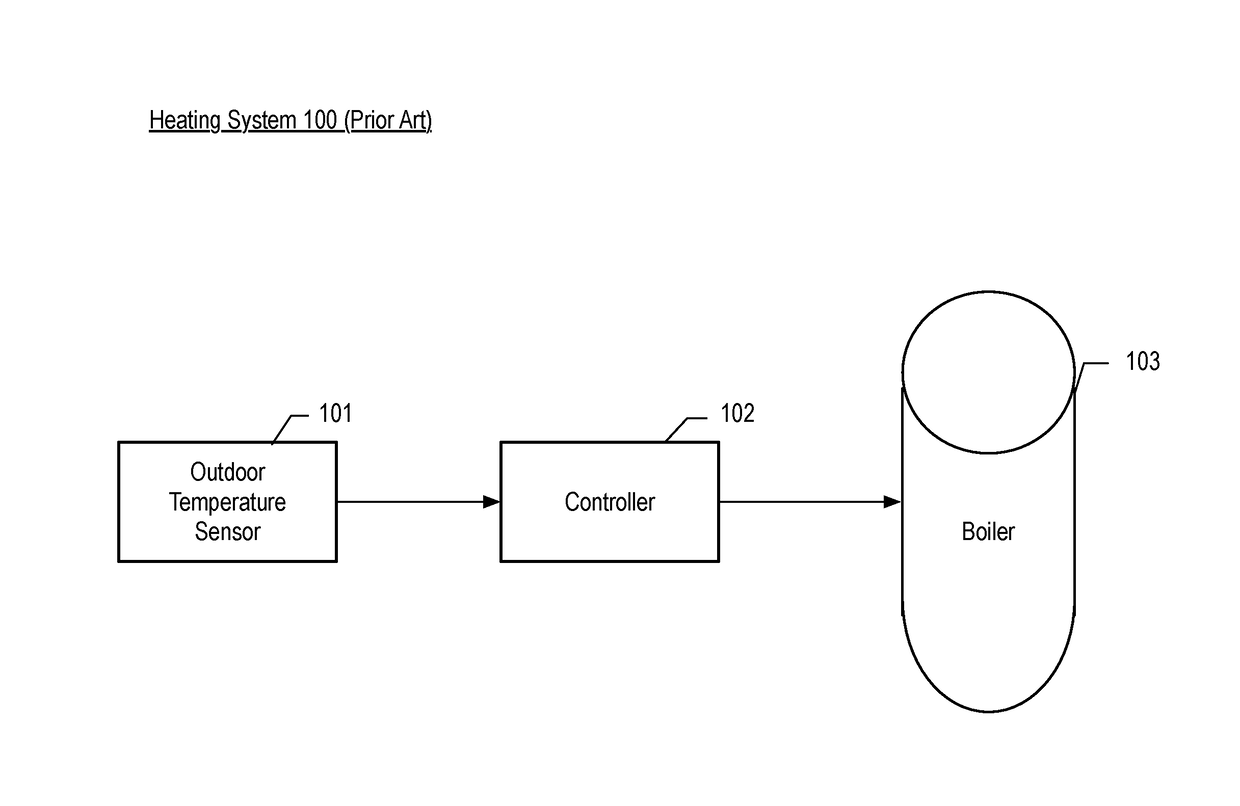
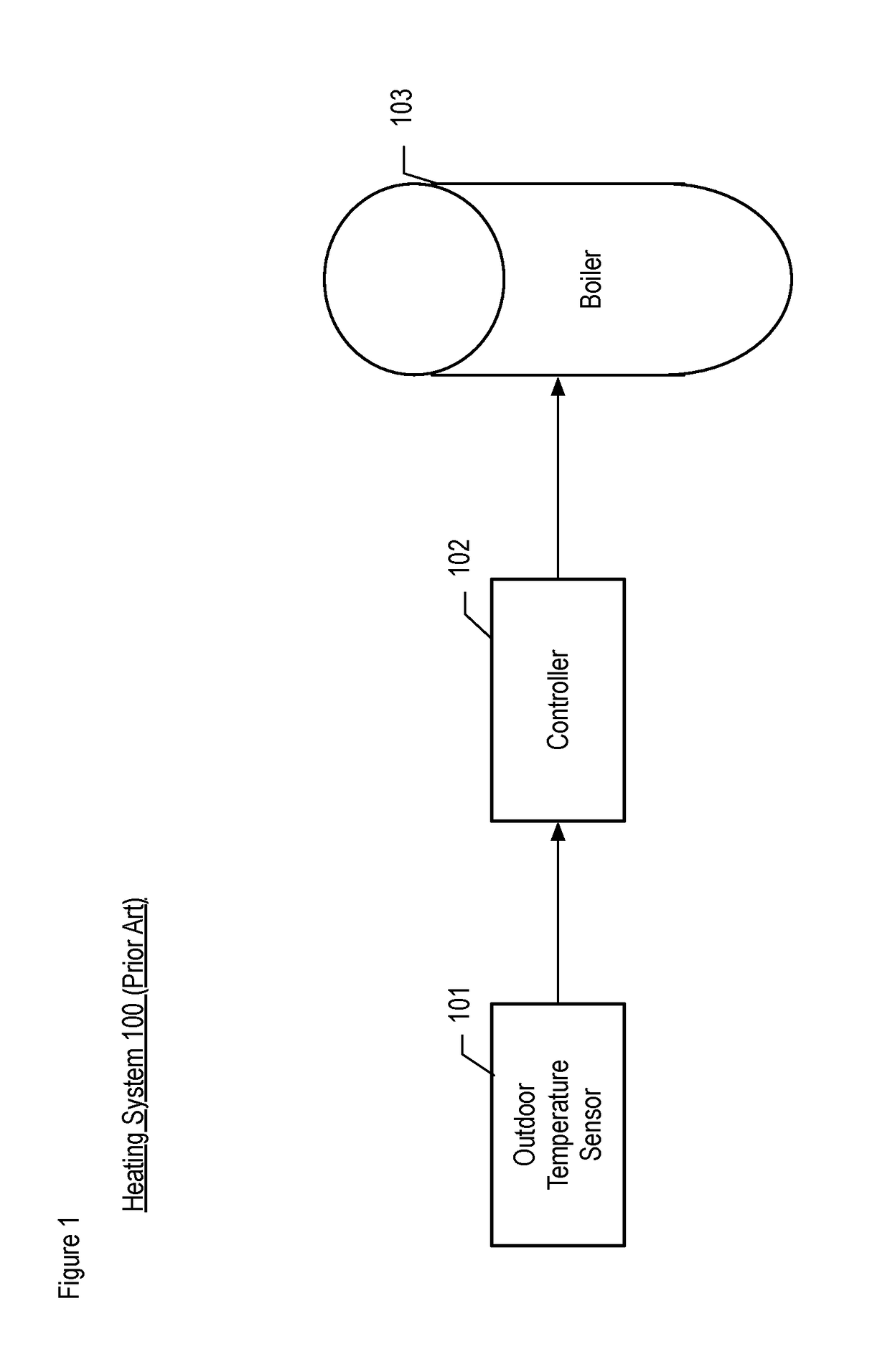
[0026]FIG. 1 depicts heating system 100 in accordance with the prior art. Heating system 100 is comprised of outdoor temperature sensor 101, controller 102, and boiler 103.

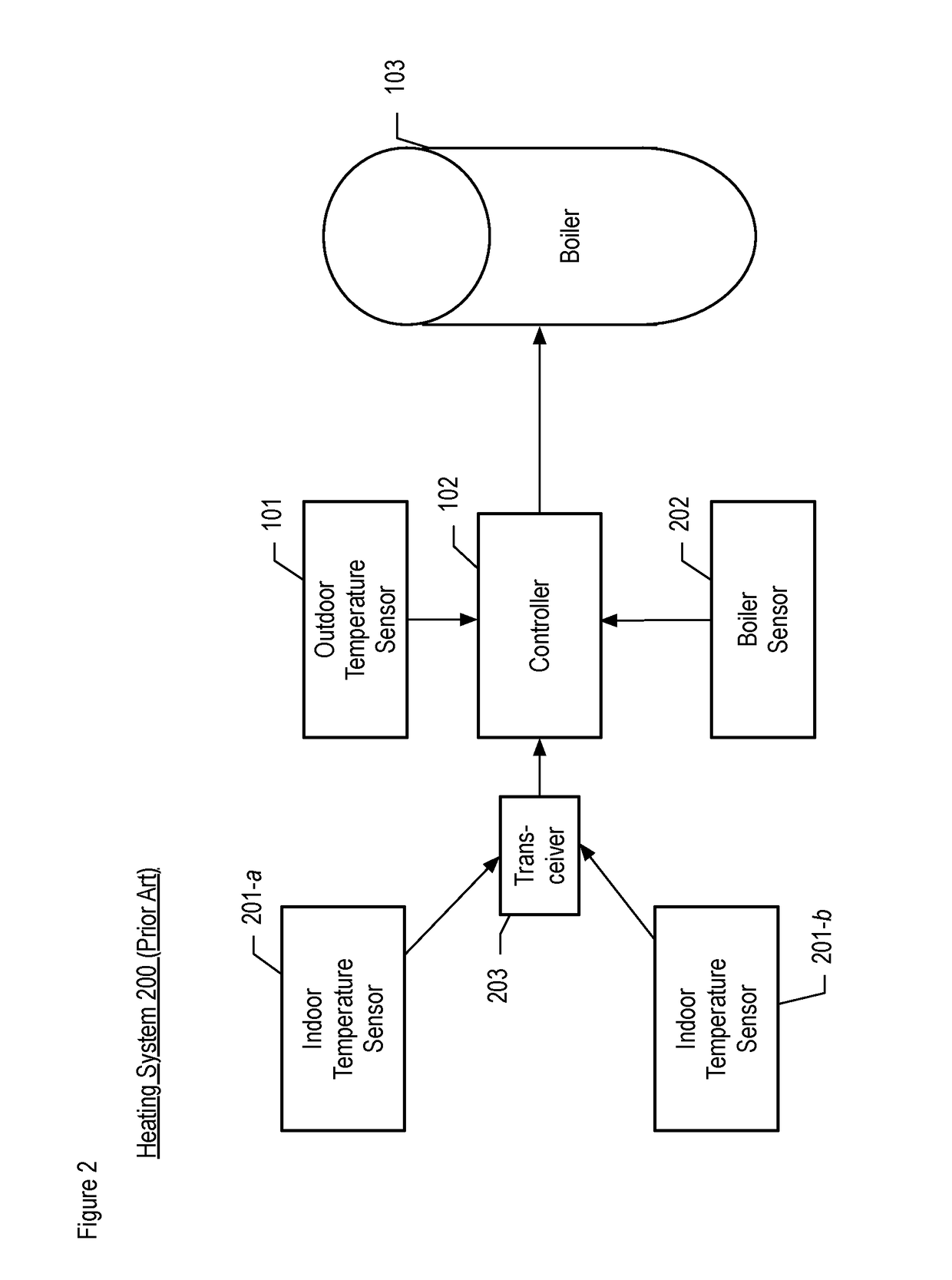
[0027]FIG. 2 depicts heating system 200 in accordance with the prior art. Heating system 200 is comprised of and outdoor temperature sensor 101, indoor temperature sensors 201-a &201-b, controller 102, a boiler sensor 202, and boiler 103.

[0028]In accordance with the illustrative embodiment of the prior art, pipe steam systems operate by activating a boiler for an initial phase to build pressure in the heating system. This typically corresponds with a preset condensate temperature, for example 150° F. After reaching the preset temperature, the boiler is then left on for a preset amount of time corresponding to the outdoor weather. The building then reaches and maintain a desired average indoor temperature, for example 72° F. After the preset boiler runtime has elapsed, the boiler shuts off. Almost all heating syste...


PUM


Abstract

A method for boiler control and a monitoring system is disclosed. The present invention provides superior boiler control compared with earlier and current systems. In accordance with the illustrative embodiment of the present invention, the heating system is improved by utilizing computer and telecommunications technology to provide more accurate boiler control and to automatically identify problems in the system.

Description

FIELD OF THE INVENTION[0001]The present invention relates to temperature control units in general, and, more particularly, to boiler controls.BACKGROUND OF THE INVENTION[0002]Temperature control for buildings has been an issue since buildings themselves have existed. Keeping from freezing is the primary purpose of shelter from time immemorial and as building increase in size and complexity, heating these buildings becomes more difficult.[0003]Almost all heating systems operate by turning on a heating element, such as a boiler, getting that element up to a particular temperature or pressure, and running the element for a particular time until the radiated heat reaches a desired temperature inside a given space.[0004]One of the systems of heating a building is the use of steam heat. When using steam heat, a boiler is filled with water, the boiler is then heated to turn the water into water vapor. The water vapor then flows through a building, and the heat from the hot water vapor is t...

Claims


Application Information

Patent Timeline
Patent Type & Authority Applications(United States)
IPC IPC(8): F24D19/10
CPCF24D2220/042F24D19/1003
Inventor HOFFMAN, LEECARLETON, JEFFCARLETON, DANIEL
Owner SMART ENERGY BOX LLC
Why Eureka
Try Eureka