Conveyor-type grilling appliance for cooking or re-thermalizing food with multiple independently controlled sets of conveyors defining multiple independently controlled cooking lanes

Active Publication Date: 2017-04-13
A J ANTUNES & CO
View PDF0 Cites 8 Cited by
  • Summary
  • Abstract
  • Description
  • Claims
  • Application Information

AI Technical Summary

Benefits of technology

[0005]The overall objectives of the present invention are to provide a new and improved grilling appliance for cooking food which will overcome and eliminate the various disadvantages and drawbacks characteristic of conventional grilling apparatus, equipment, or appliances for cooking food, to provide a new and improved grilling appliance for cooking food which will effectively overcome and eliminate the poor cooking results often encountered with conventional grilling appliances, apparatus, or equipment for cooking food, to provide a new and improved grilling appliance which will enhance the efficiency of the food-cooking procedure or process, and to provide a new and improved grilling appliance which will automatically controt the food-cooking procedure or process, from the beginning of the food-cooking cycle to the end of the food cooking cycle, so as to provide a properly cooked and tasty end food product, and to provide a new and improved grilling appliance which can simultaneously prepare or cook or re-thermalize different types of foods.
[0006]The foregoing and other objectives are achieved in accordance with the teachings and principles of the present invention through the provision of a new and improved grilling appliance for cooking food wherein the grilling appliance comprises upper and lower endless conveyor belts which are routed over and around upper and lower heated platens and which are fabricated, for example, from PTFE, polytetrafluoroethylene, which are adapted to be disposed in contact with the food articles being cooked, and yet the food articles will not adhere or st

Problems solved by technology

The operational drawback or disadvantage of such apparatus, equipment, or appliances, however, is the fact that the cooking time is effectively monitored and necessarily controlled by means of the personnel doing th

Method used


Image

  • Conveyor-type grilling appliance for cooking or re-thermalizing food with multiple independently controlled sets of conveyors defining multiple independently controlled cooking lanes
  • Conveyor-type grilling appliance for cooking or re-thermalizing food with multiple independently controlled sets of conveyors defining multiple independently controlled cooking lanes
  • Conveyor-type grilling appliance for cooking or re-thermalizing food with multiple independently controlled sets of conveyors defining multiple independently controlled cooking lanes

Examples


Embodiment Construction

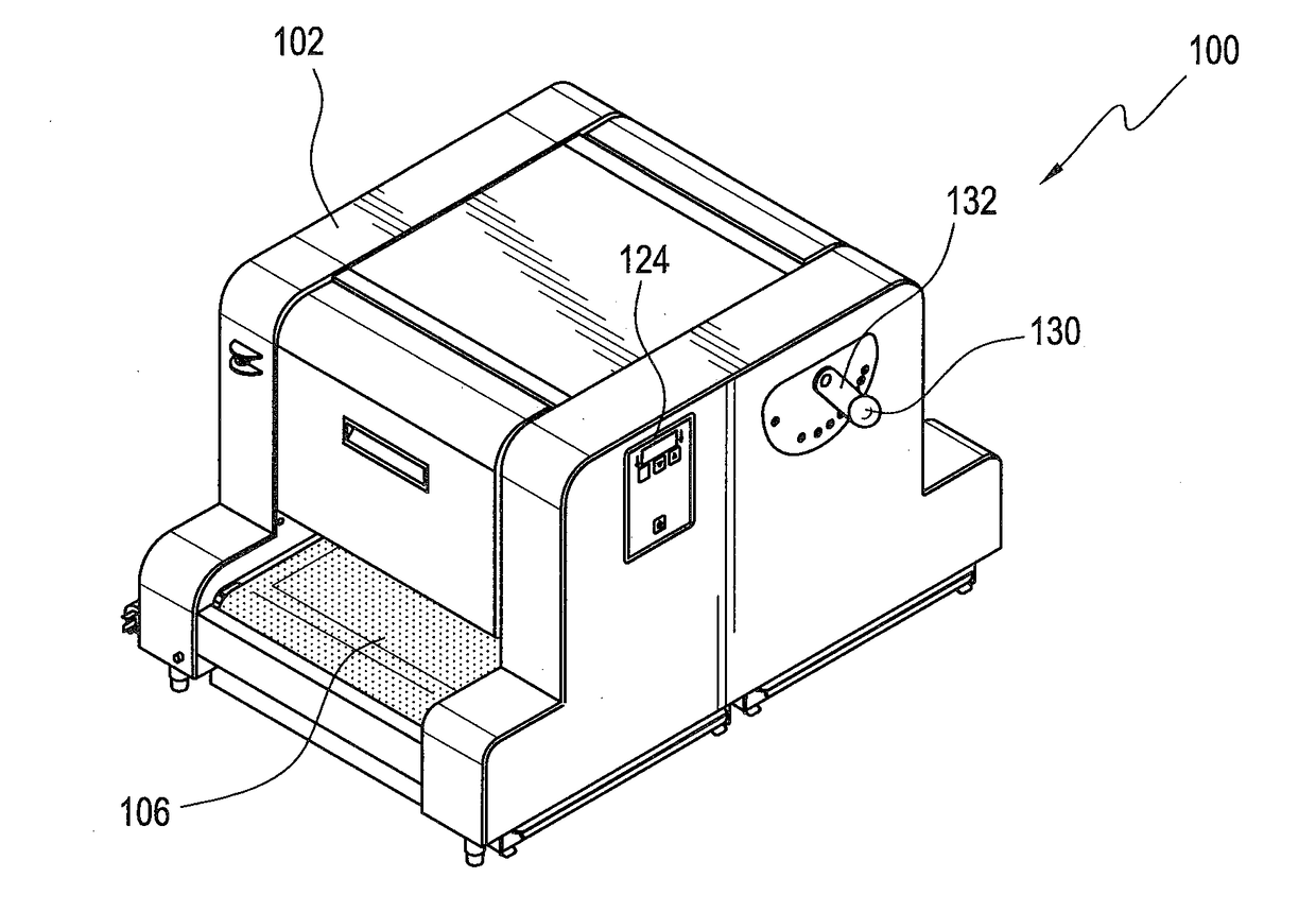
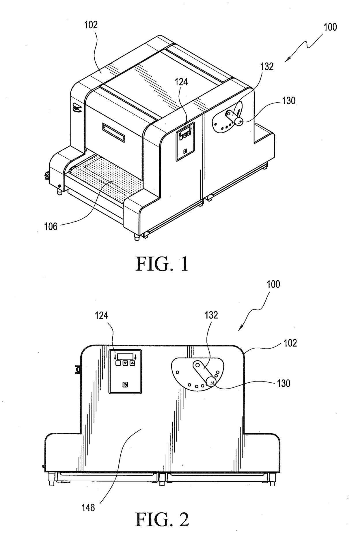
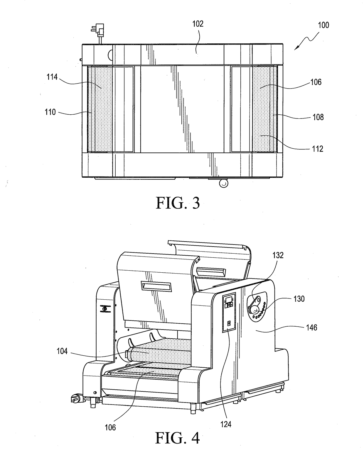
[0026]Referring now to the drawings, and more particularly to FIGS. 1-5 thereof, a first embodiment of a new and improved conveyor-type grilling appliance for cooking food is disclosed and is generally indicated by the reference character 100. More particularly, it is seen that the new and improved conveyor-type grilling appliance 100 comprises a housing 102 within which a pair upper and lower conveyor belts 104, 106 are disposed as can best be appreciated from FIGS. 1,3, and 4. The upper and lower conveyor belts 104,106 are endless conveyor belts that flow through the housing 102 from a food product input or entrance end 108 of the housing 102 to a food product output or exit / discharge end 110 of the housing 102. The upper conveyor belt 104 is wholly enclosed within the housing 102, while the opposite ends of the lower conveyor belt 106 extend beyond each end of the housing 102. In this manner, a first movable platform region 112 of the lower conveyor belt 106 is defined at the foo...


PUM


Abstract

A grilling appliance is disclosed for preparing various different types of food wherein the food is conveyed through the appliance, from a food insert end of the appliance to a food removal end of the appliance, by means of continuously movable flow-through upper and lower cooperating conveyors operatively associated with platen-type heating members over which the upper and lower conveyors are conveyed so as to be heated by the platen-type heating members and thereby, in turn, heat, brown, or carmelize the food as desired or required. Multiple independently controlled conveyor sets define multiple independently controlled conveyor cooking lanes within the appliance.

Description

CROSS-REFERENCE TO RELATED APPLICATION[0001]This patent application is a non-provisional patent application conversion of U.S. Provisional Patent Application Ser. No. 62 / 240,553 which was filed on Oct. 13, 2015, the priority benefits of which are hereby claimed.FIELD OF THE INVENTION[0002]The present invention relates generally to food preparation apparatus, equipment, or appliances, and more particularly to a grilling appliance for preparing various different types of food wherein the food is conveyed through the appliance, from a food insert end of the appliance to a food removal end of the appliance, by means of continuously movable flow-through upper and lower cooperating conveyors operatively associated with platen-type heating members over which the upper and lower conveyors are conveyed so as to be heated by the platen-type heating members and thereby, in turn, heat, brown, or carmelize the food as desired or required. Multiple independently controlled conveyors, for defining...

Claims


Application Information

Patent Timeline
IPC IPC(8): A47J37/04A47J37/06
CPCA47J37/06A47J37/045A21B1/48
Inventor PATEL, DIPANPATEL, BHUPENDRA R.PATEL, JIGNESHBUCHLER, JAMES R.VEGA, FRANCISCOVEGA, IGNACIOPANASIK, CHERYL L.CUCCHI, ROBERT LEWIS
Owner A J ANTUNES & CO
Why Eureka
Try Eureka