Illumination sources for multicore fiber endoscopes

a multi-core fiber and endoscope technology, applied in the field of endoscopy, can solve the problems of difficult operation of the endoscope, confined illumination, detection and treatment,

Active Publication Date: 2017-04-13
Z SQUARE LTD
View PDF0 Cites 22 Cited by
  • Summary
  • Abstract
  • Description
  • Claims
  • Application Information

AI Technical Summary

Benefits of technology

[0007]One aspect of the present invention provides an endoscope having a distal tip and a proximal tip, the endoscope comprising at least one multicore fiber module comprising at least one hundred cores distributed at a fill factor smaller than ¼, an illumination source coupled to the at least one multicore fiber module and configured to deliver illumination thereto, at least one optical element, in optical communication with the cores, at the distal tip, a detector, in optical communication with the cores, at the proximal tip, and a processor configured to receive images from the detector; wherein the endoscope is configured to implement super-resolved imaging by micro scanning over a pitch distance between the cores, and wherein the endoscope is configured to implement three dimensional sensing by handling the cores group-wise with respect to radiation delivered therethrough, and to at least one of: enhance, by configuring the at least one optical element, a field of view of the endoscope beyond a region facing the cores at the distal tip, and enhance, by configuring the at least one optical element, a depth of field of the endoscope beyond a region congruent to the distal tip.

Problems solved by technology

Endoscope operations are challenging in that illumination, detection and treatment are confined to long and narrow operations modes.

Method used


Image

  • Illumination sources for multicore fiber endoscopes
  • Illumination sources for multicore fiber endoscopes
  • Illumination sources for multicore fiber endoscopes

Examples


Embodiment Construction

[0024]Prior to the detailed description being set forth, it may be helpful to set forth definitions of certain terms that will be used hereinafter.

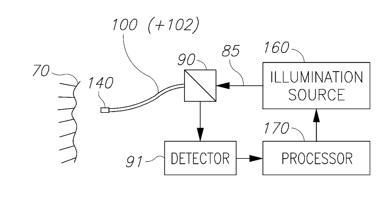
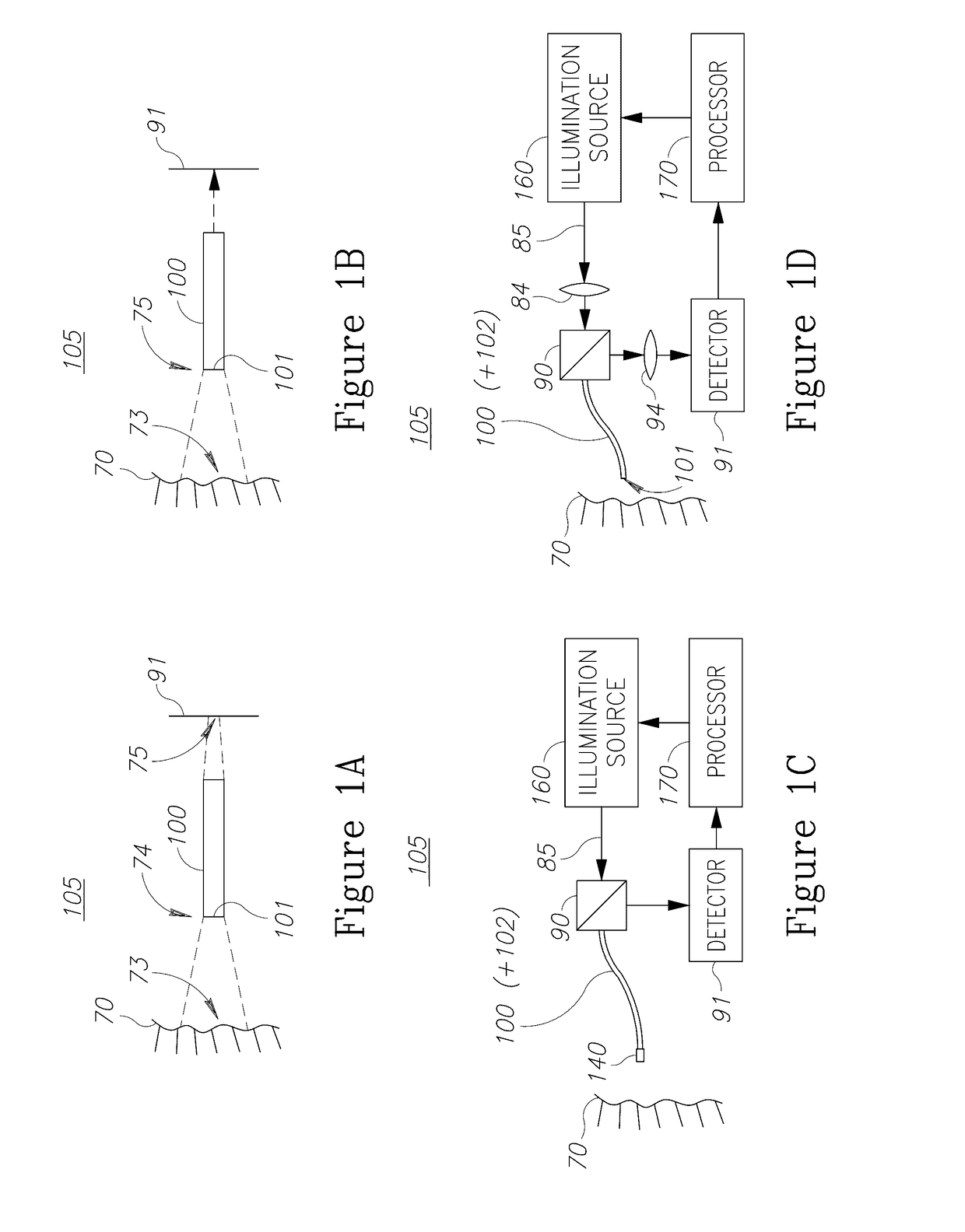
[0025]The terms “distal” and “proximal” as used in this application refer to the ends of the endoscope. The end and associated parts of the endoscope which are far from the endoscope's interface (detector or eye) and close to the imaged tissue and to its surroundings is termed the distal end, while the end and associated parts of the endoscope which are close to the endoscope's interface and are remote from the imaged tissue, being typically outside the body is termed the proximal end. The term “reflected” as used in this application refers to a change in a direction of an illumination wavefront which impacts one or more imaged object or tissue. The term “reflection” is understood broadly as any radiation gathered by the fiber, irrespective of the source of the illumination which is reflected by the object(s) and / or tissue(s).

[0026]The te...


PUM


Abstract

Endoscopes, multicore endoscope fibers and configuration and operation methods are provided. The fibers may have hundreds or thousands of cores and possibly incorporate working channel(s) and additional fibers. The fiber may be used at different optical configurations to capture images of tissue and objects at the distal tip and to enhance a wide range of optical characteristics of the images such as resolution, field of view, depth of field, wavelength ranges etc. Near-field imaging as well as far-field imaging may be implemented in the endoscopes and the respective optical features may be utilized to optimize imaging. Optical elements may be used at the distal fiber tip, or the distal fiber tip may be lens-less. Diagnostics and optical treatment feedback loops may be implemented and illumination may be adapted to yield full color images, depth estimation, enhanced field of views and / or depths of field, and additional diagnostic data.

Description

CROSS REFERENCE TO RELATED APPLICATIONS[0001]This application is a continuation in part of U.S. patent application Ser. No. 14 / 805,915 filed on Jul. 22, 2015, which claims priority under 35 U.S.C. §119 to U.S. Provisional Patent Application No. 62 / 028,346 filed on Jul. 24, 2014 and to U.S. Provisional Patent Application No. 62 / 119,832 filed on Feb. 24, 2015, all of which are incorporated herein by reference in their entireties.BACKGROUND OF THE INVENTION[0002]1. Technical Field[0003]The present invention relates to the field of endoscopy, and more particularly, to multicore fiber endoscopes.[0004]2. Discussion of Related Art[0005]Endoscopes in various configurations allow efficient treatment of a range of medical problems, as well as means for manipulating different situations with limited access. Endoscope operations are challenging in that illumination, detection and treatment are confined to long and narrow operations modes. Fiber optics technology is a central enabler for such t...

Claims


Application Information

Patent Timeline
Patent Type & Authority Applications(United States)
IPC IPC(8): A61B1/07H04N13/00H04N5/225G02B23/26A61B1/06G02B26/10G02B27/00G02B27/48G02B6/02A61B1/00H04N13/02G02B23/24
CPCA61B1/07H04N2005/2255H04N13/0296H04N13/0048H04N5/2254G02B23/26G02B23/2423G02B26/103G02B27/0075G02B27/48G02B23/2469G02B6/02042A61B1/00167A61B1/00087A61B1/00096A61B1/00193A61B1/0676A61B1/00117H04N13/0253A61B1/0017G02B6/06G02B27/283H04N13/161H04N13/254H04N13/296H04N23/50H04N23/555
Inventor SHAHMOON, ASAFZALEVSKY, ZEEV
Owner Z SQUARE LTD
Why Eureka
Try Eureka