Modular Sensing Device

a module and sensing technology, applied in the direction of coupling device connection, television system, instruments, etc., can solve the problem of increasing the current that can be transferred between modules, and achieve the effect of preventing water and/or pin electrolysis

a module and sensing technology, applied in the direction of coupling device connection, television system, instruments, etc., can solve the problem of increasing the current that can be transferred between modules, and achieve the effect of preventing water and/or pin electrolysis

US20170102606A1Inactive Publication Date: 2017-04-13MOHAWK GRP INC

Image

  • Modular Sensing Device
  • Modular Sensing Device
  • Modular Sensing Device

Examples


Embodiment Construction

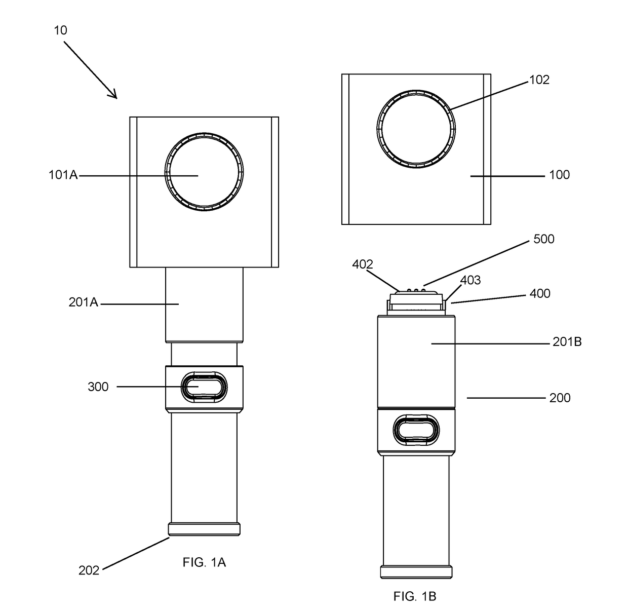
[0020]FIG. 1A shows a front view of an optical head module connected to the handle mechanism.

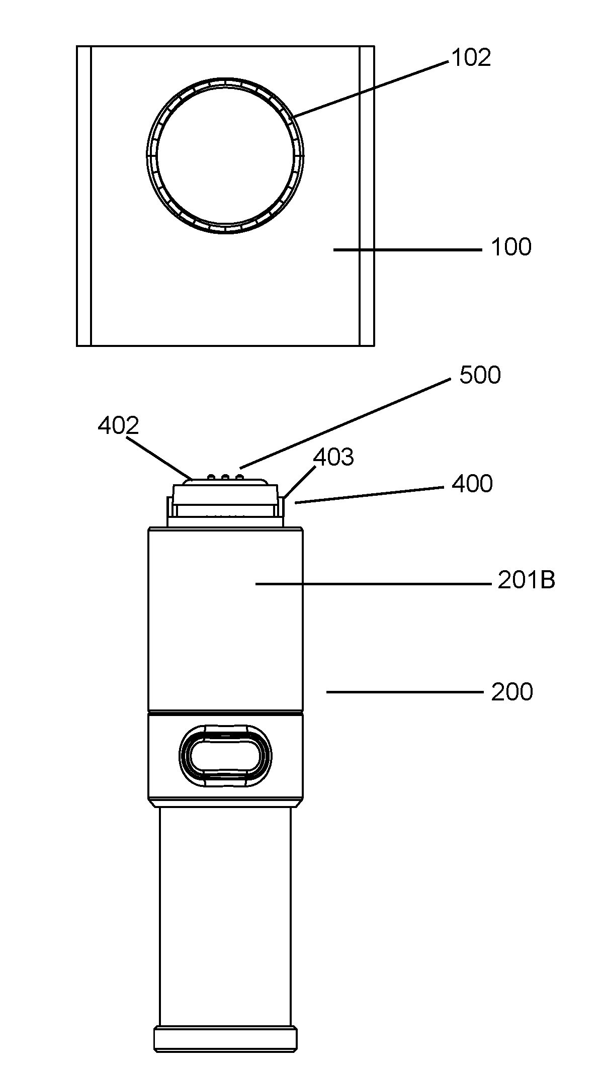
[0021]FIG. 1B shows a front view of the optical head module disconnected from the handle mechanism.

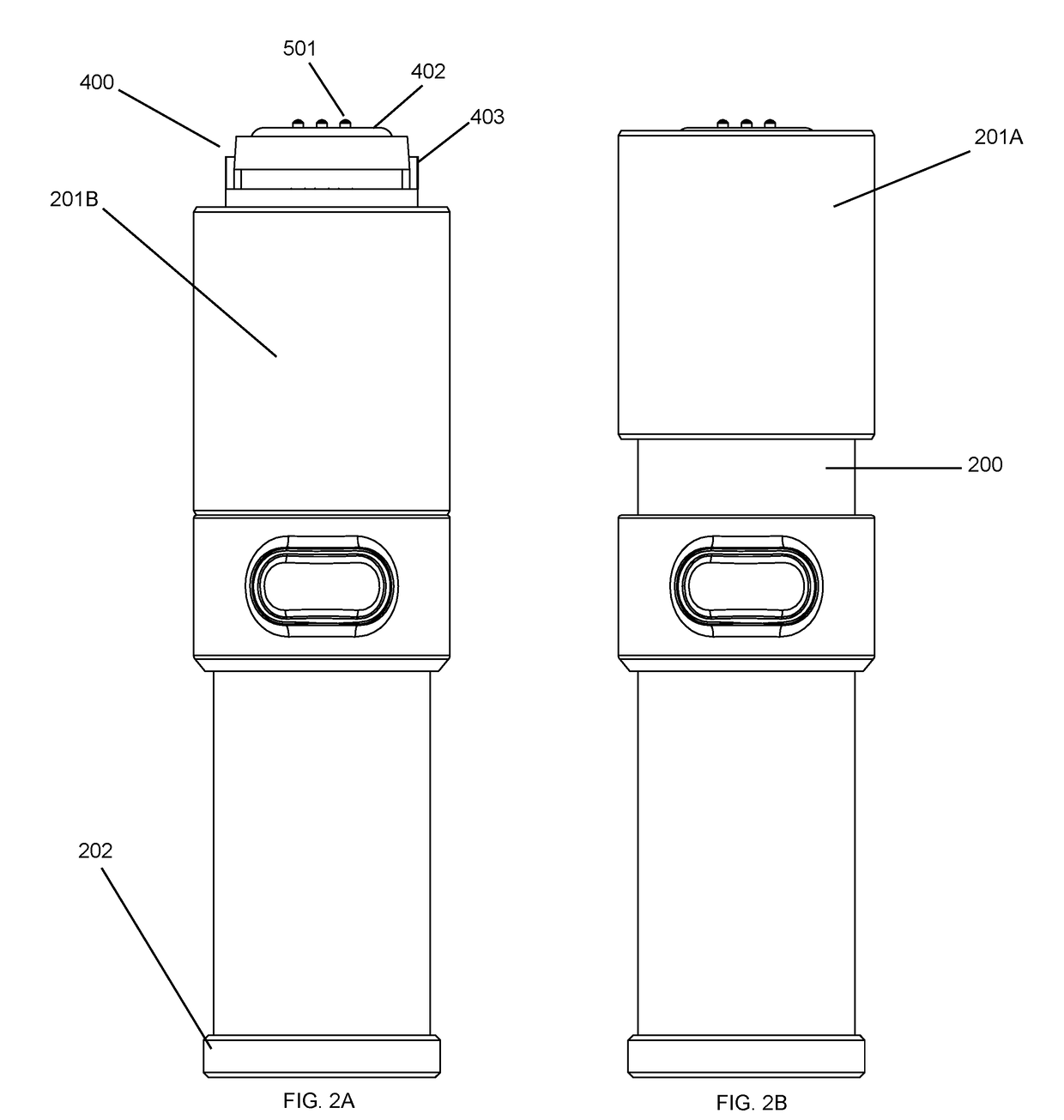
[0022]FIGS. 2A and 2B show front views of the handle mechanism with the locking sleeve down exposing the pin pad and seal, and sleeve in the upward position with only the tips of the pins exposed.

[0023]FIGS. 3A, 3B, and 3C show a top, front, and bottom view of the handle mechanism with a sleeve and bayonet mount mating system.

[0024]FIG. 4 shows a perspective view of the handle mechanism with a sleeve and bayonet mount mating system.

[0025]FIG. 5A shows a front view of a square optical head module with cross-section C-C.

[0026]FIG. 5B shows a side perspective view of the data, power, and ground pin insertion on the optical head module at cross-section C-C and a bayonet slot.

[0027]FIG. 5C shows a bottom view of the pin insertion and locking joint on the square optical head module with a bayonet mou...


PUM


Abstract

This invention relates to a device comprised of at least two interchangeable modules, wherein at least one module has a power source and / or data storage unit and can transmit power and / or data to all of the electrically and mechanically mated modules. The device is designed for use in extreme weather environments, such as but not limited to, snow, rain, at elevation, and / or under pressure. In addition, each mating point between the at least two modules is waterproof. In a preferred embodiment, the device is comprised of a first module that is an optical head, with at least two optical lenses and can sense and capture image data. A second module is a handle comprised of a battery. When the first and second modules are electrically and mechanically mated, the two modules are secure and waterproof and the device operates as a 360° optical camera with an interchangeable power handle module.

Description

FIELD OF THE INVENTION[0001]This invention relates to the fields of power and data transmission and optical sensing devices. More specifically, the present invention relates to a device comprised of at least two modular components, wherein at least one module has a power source and / or data storage unit and can transmit both data and / or power to all of the modules in the device when the at least two modules are mechanically and electrically connected.[0002]The device is designed for use in extreme weather environments, such as but not limited to: snow, rain, at elevation, and / or in a pressurized environment. In addition, each mating point between the at least two modules is waterproof.[0003]In a preferred embodiment, the device is designed such that a first module has a sensor such as, but not limited to, an optical head that can mechanically and electrically mate to a second module that could function have the following features, including but not limited to a: base, illumination po...

Claims


Application Information

Patent Timeline
13 Apr 2017
Publication
US20170102606A1
IPC
G03B17/56; H04N5/232; H01R13/04; H01R13/52; H01R13/24; G01D11/24; H04N5/225
CPC
G03B17/563; G01D11/245; H04N5/23238; H01R13/04; H04N5/23209; H01R13/5219; H01R13/24; H04N5/2253
Inventors
PAVIS, SARAH; SUTTON, DAVID MICHAEL