Electromechanical brake system based on automobile bus and automobile

An electro-mechanical braking, automotive bus technology, applied in the direction of brakes, brake transmissions, vehicle components, etc., to achieve the effect of reducing volume and weight

Active Publication Date: 2012-11-21
CHERY AUTOMOBILE CO LTD
View PDF4 Cites 41 Cited by
  • Summary
  • Abstract
  • Description
  • Claims
  • Application Information

AI Technical Summary

Problems solved by technology

[0004] The technical problem to be solved by the present invention is to provide a hydraulic braking system with simple structure, small volume, convenient installation, low cost, fast braking response and good stability during braking, aiming at the above-mentioned deficiencies in the prior art hydraulic braking system. Pollution-free electromechanical braking system based on automobile bus, and automobiles using said braking system

Method used


Image

  • Electromechanical brake system based on automobile bus and automobile
  • Electromechanical brake system based on automobile bus and automobile
  • Electromechanical brake system based on automobile bus and automobile

Examples


Embodiment 1

[0061] In this embodiment, the electromechanical braking system based on the automobile bus is applied to a four-wheeled vehicle, and the four-wheeled vehicle includes four wheels, which are respectively a left front wheel, a right front wheel, a left rear wheel and a right rear wheel .

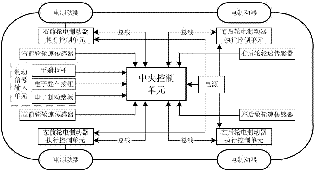
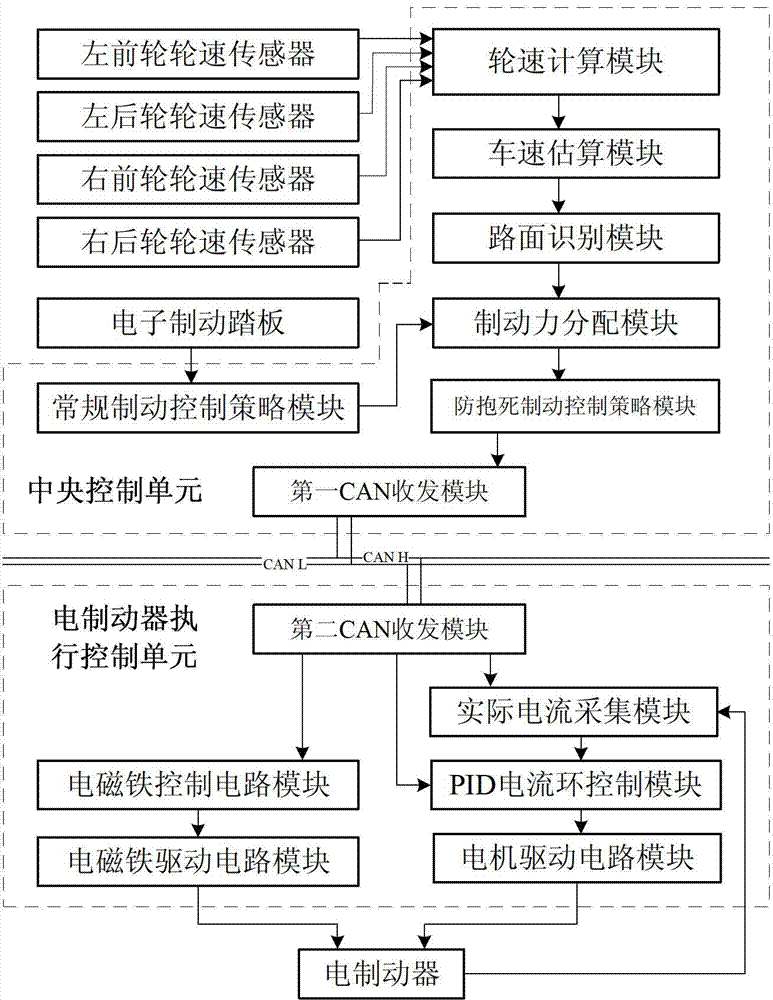
[0062] Such as figure 1 As shown, the electromechanical brake system based on the automobile bus (hereinafter referred to as the brake system) includes a brake signal input unit, a central control unit, four electric brake execution control units, four electric brakes and a power supply. Wherein, each electric brake execution control unit corresponds to an electric brake, and each electric brake corresponds to a wheel, and the four electric brake execution control units are respectively the left front wheel electric brake execution control unit and the right front wheel electric brake execution control unit , left rear wheel electric brake execution control unit, right rear wheel electric br...

Embodiment 2

[0112] The difference between this embodiment and Embodiment 1 is that the brake signal input unit does not include an electronic parking switch.

[0113] Other structures in this embodiment are the same as those in Embodiment 1, and will not be repeated here.

Embodiment 3

[0115] The difference between this embodiment and Embodiment 1 is that the central control unit does not include the anti-lock braking control strategy module.

[0116] Other structures in this embodiment are the same as those in Embodiment 1, and will not be repeated here.


PUM


Abstract

The invention provides an electromechanical brake system based on an automobile bus. The electromechanical brake system based on the automobile bus comprises a brake signal input unit, a central control unit, a plurality of electric brake execution control units and a plurality of electric brakes, wherein the brake signal input unit is used for receiving brake signals and outputting the brake signals to the central control unit in real time; the central control unit is used for outputting multiple paths of brake motor target current signals to corresponding electric brake execution control units in real time according to the received brake signals; the electric brake execution control units are used for respectively driving and controlling corresponding electric brakes in real time according to the received brake motor target current signals; and the electric brakes are used for braking corresponding wheels. Correspondingly, the invention additionally provides an automobile with the brake system. The electromechanical brake system provided by the invention has the advantages of simple structure, small size, convenience in installation, low cost, quick brake response, good stability when used for braking , no pollution and the like.

Description

technical field [0001] The invention belongs to the technical field of automobile manufacturing, and in particular relates to an electromechanical brake (EMB, Electro Mechanical Brake) system based on an automobile bus, and an automobile using the electromechanical brake system. Background technique [0002] With the rapid development of the automobile industry and the continuous improvement of the driving performance of automobiles, people pay more and more attention to the safety of automobiles. Braking performance is one of the important performances of automobiles. The braking performance of automobiles is directly related to the safety of traffic. safety. [0003] At present, most vehicle braking systems at home and abroad are still based on hydraulic braking systems to achieve vehicle braking. However, the traditional hydraulic braking system has defects such as complex structure, inconvenient installation, high price, and slow braking response. Contents of the inve...

Claims


Application Information

Patent Timeline
Patent Type & Authority Applications(China)
IPC IPC(8): B60T8/1761B60T8/26B60T13/74
CPCB60T13/741
Inventor 王陆林陈军张世兵段山保高国兴
Owner CHERY AUTOMOBILE CO LTD
Why Eureka
Try Eureka