Secure infrastructure for path determination system

a path and infrastructure technology, applied in the direction of transmission, forecasting, electrical equipment, etc., can solve the problems of project delay, cost overrun, litigation, and a wide range of other problems, and achieve the effect of enhancing visualization and reducing costs

Inactive Publication Date: 2006-01-26
TRIMBLE PLANNING SOLUTIONS
View PDF15 Cites 47 Cited by
  • Summary
  • Abstract
  • Description
  • Claims
  • Application Information

AI Technical Summary

Benefits of technology

[0037] In an embodiment the paths may be developed using “what if” scenarios by revising constraints or revising the optimization seeding. In an embodiment, one path may be selected from an existing set of paths and may be used as a seed for further optimization runs with different parameters. This may yield a refined path. In an embodiment changes may be made and new files sent to the server-based application that may generate a different set of possible paths. The “what if” iteration process may uncover a path that may yield a lesser cost, more acceptable path, or other different path. In an embodiment the “what if” iteration may be performed to create paths that meet the engineering requirements as often as the user chooses. In an embodiment the iteration process may be completed signific

Problems solved by technology

Failing to account properly for a constraint can result in project delays, cost overruns, litigation, and a wide range of other problems.
This process can take a significant amount of time to create a center line for the path, calculate all of the costs associated with the path, and then review this information within the constraints of a budget.
The process of manual selection of a path can only produce one path at a time, and the time and resource constraints of a project usually limit the number of path options to be considered.
The path is determined manually by the planner, without optimization, and it does not support simultaneous consideration of engineering, cost, environmental,

Method used


Image

  • Secure infrastructure for path determination system
  • Secure infrastructure for path determination system
  • Secure infrastructure for path determination system

Examples


Embodiment Construction

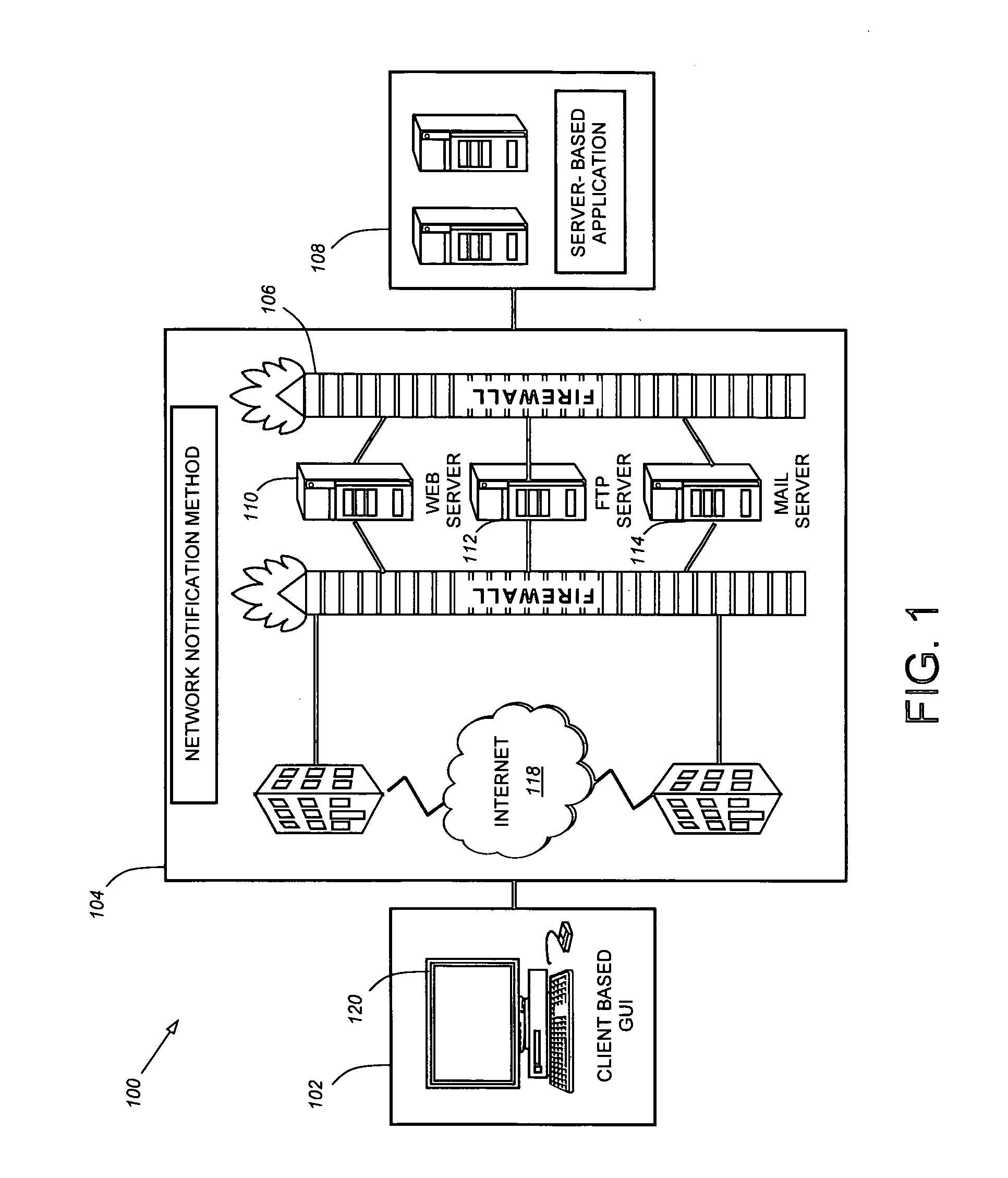
[0097] Referring to FIG. 1 a block diagram is shown of a system 100 for supporting the methods and systems described herein. The system 100 includes a client-based application 102 having a graphical user interface (GUI) 120 and a server-based application 108. The client-based application 102 with the GUI 120 is connected to the network facility 104. The network facility 104 may use or include any conventional network facility for transporting data, such as the Internet 118, a local area network, a wide area network, a router, a hub, an access point, a wireless network, a Bluetooth network, a cellular network, a DSL network, a cable network, or any other kind of network facility. The data can be sent via a web server 110, an FTP server 112, an HTTP server, a mail server 114, a firewall 106, or other form of server and system protection. The client-based application 102 connects to the server-based application 108 through the network facility 104. For example, the client-based applica...


PUM


Abstract

Aspects of the present invention relate to providing control for a secure infrastructure of a path determination system. In embodiments, methods and systems are provided for controlling objects in a computer-based system. The methods and systems may involve storing an object in the system, the object being related to data about the path or project, assigning an encryption key for each aspect of the system or object desired to be controlled, encrypting each aspect of the system or object desired to be controlled, requiring entry of the encryption key corresponding to each aspect of the system or object desired to be released from the control, and distributing the encryption key.

Description

RELATED APPLICATIONS [0001] This application claims the benefit of the following commonly owned U.S. provisional patent applications, each of which is incorporated herein by reference in its entirety: U.S. Prov. App. No. 60 / 569,897, filed May 11, 2004 and entitled “Methods and Systems for optimization of Corridors, Routes, Alignments and Paths for Linear Infratsructure”; U.S. Prov. App. No. 60 / 669,056, filed Apr. 7, 2005 and entitled “Methods and Systems for Optimization of Corridors, Routes Alignments, and Paths”; and Attorney Docket No. QNTM-0001-P60, filed May 5, 2005 and entitled “Terrain Design and Mapping Systems”. [0002] This application is a continuation-in-part of commonly owned Attorney Docket No. QNTM-0002-P01, filed May 6, 2005 and entitled “Path Analysis System with Client and Server-Side Applications.” This application is incorporated by reference herein in its entirety. [0003] This application is related to the following commonly owned, co-pending applications filed o...

Claims


Application Information

Patent Timeline
IPC IPC(8): H04L9/00
CPCG06Q10/047H04L9/14
Inventor GIPPS, PETERNIXON, ROBERTGRIFFITHS, ALAN
Owner TRIMBLE PLANNING SOLUTIONS
Why Eureka
Try Eureka