Eureka AIR delivers breakthrough ideas for toughest innovation challenges, trusted by R&D personnel around the world.

Vibrating fitness ball

Active Publication Date: 2017-04-20
HYPERICE IP SUBCO LLC
View PDF11 Cites 19 Cited by
  • Summary
  • Abstract
  • Description
  • Claims
  • Application Information

AI Technical Summary

Benefits of technology

The patent text describes a vibration generation device that can be easily gripped and used as a therapeutic massage device. The device includes a spherical ball with two hemispheres that support a motor and battery assembly. The motor causes the rotating eccentric masses to produce vibrations that are communicated from the hands to the arms and shoulders. The device can also be used as a portable vibration generation apparatus. The technical effects of the patent text include a vibration generation device that is easy to use, provides strong vibrations, and can be used as a therapeutic massage device.

Problems solved by technology

The configuration of vibrating dumbbells limits the utility of such devices because the devices must be gripped securely using the cylindrical bar interconnecting the two end weights.
Such devices also do not vibrate with sufficient force to provide the desirable benefits of vibration.
Vibrating rollers are used for therapeutic massage; however, rollers typically spread the vibrations over relatively large areas of a body and do not allow the vibratory effect to be concentrated in smaller areas to focus the therapeutic effect on a particular muscle or myofascial connective tissue.

Method used


Image

  • Vibrating fitness ball
  • Vibrating fitness ball
  • Vibrating fitness ball

Examples


Embodiment Construction

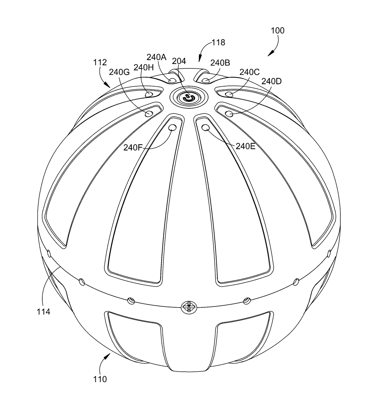
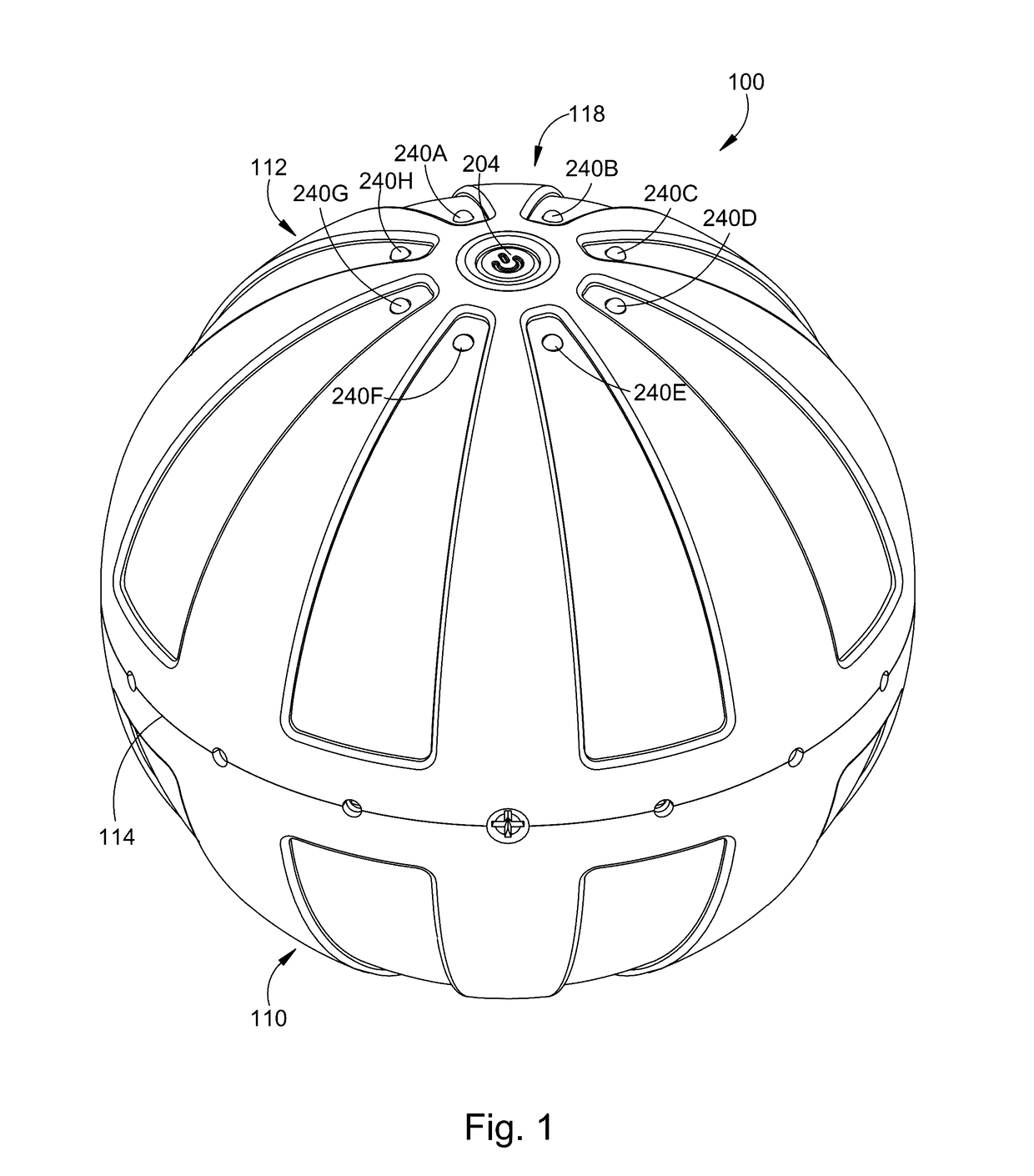
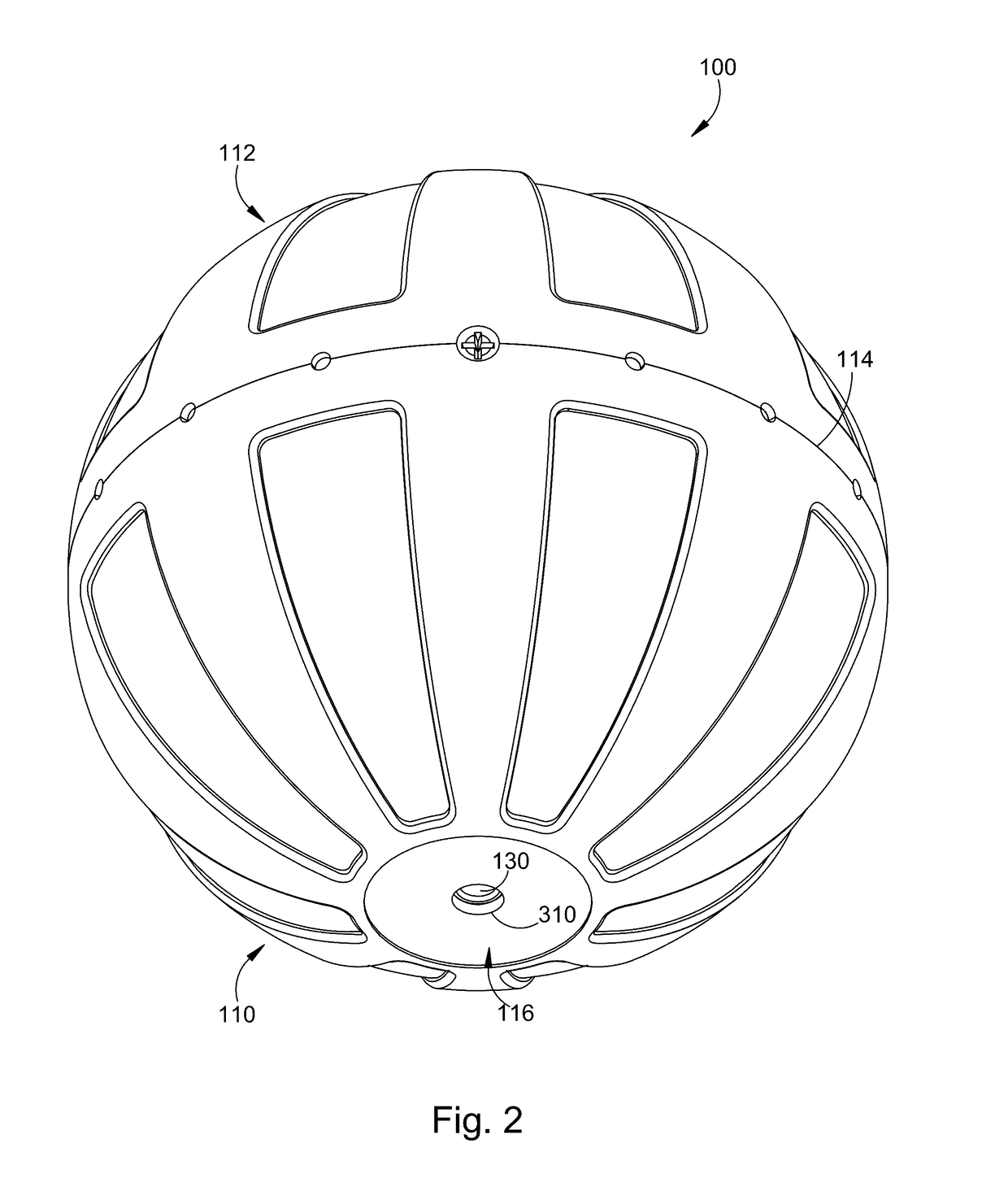
[0042]A spherical fitness ball 100 is illustrated in a top perspective view in FIG. 1 and in a bottom perspective view in FIG. 2. The ball includes a lower (first) hemisphere 110 and an upper (second) hemisphere 112. The lower hemisphere and the upper hemisphere are joined along an equatorial plane 114. The portion of the lower hemisphere farthest from the equatorial plane is referred to herein as a lower pole 116 of the fitness ball. The portion of the upper hemisphere farthest from the equatorial plane is referred to herein as an upper pole 118 of the fitness ball.

[0043]The outer features of the fitness ball 100 are illustrated in a front elevational view in FIG. 3A, in a side elevational view in FIG. 3B, in a top plan view in FIG. 3C, and in a bottom plan view in FIG. 3D. In the illustrated embodiment, the fitness ball has a diameter of approximately 5 inches, and is slightly flattened at the upper pole 118 and at the lower pole 116 of the ball. The diameter may be varied in alte...


PUM


Abstract

A fitness ball has first and second hemispheres, which are connectable to form a complete sphere. The first hemisphere supports a motor having a pair of rotatable eccentric masses at opposite ends of a common drive shaft. The second hemisphere supports a rechargeable battery pack, electronic circuitry and indicators LEDs. The electronic circuit controls the charging of the battery pack and also selectively provides electrical power from the battery pack to the motor to control the rotational speed of the motor to rotate the eccentric masses. The rotating eccentric masses cause vibrations that are communicated from the motor to the two hemispheres. The vibration frequency is controlled by the rotational speed of the motor. The hemispheres have outer covers having a configuration that is easy to grip such that the vibrations are communicated to a users hands. The ball is substantially balanced about an equatorial plane.

Description

RELATED APPLICATIONS[0001]The present application claims the benefit of priority under 35 USC §119(e) from U.S. Provisional Application No. 62 / 243,126 filed on Oct. 18, 2015, for “Vibrating Fitness Ball,” which is hereby incorporated herein by reference.FIELD OF THE INVENTION[0002]The present invention is in the field of therapeutic devices, and, more particularly, is in the field of exercise and fitness balls for massaging and toning muscles.BACKGROUND OF THE INVENTION[0003]Holding vibrating equipment as part of a fitness or therapeutic regimen has been found to provide benefits to enhance joint stability and to improve overall neuromuscular control. For example, vibrating dumbbells are available for this purpose. The configuration of vibrating dumbbells limits the utility of such devices because the devices must be gripped securely using the cylindrical bar interconnecting the two end weights. Such devices also do not vibrate with sufficient force to provide the desirable benefits...

Claims


Application Information

Patent Timeline
IPC IPC(8): A63B43/00A63B24/00A61H23/02A63B21/00
CPCA63B43/004A63B21/00178A63B21/0004A63B2213/00A61H23/02A63B2225/50A63B2207/02A63B24/0087A61H2015/0042A61H2023/029A61H2201/0192A61H2201/1261A61H2201/1284A61H2201/1623A61H2201/164A61H2201/1669A61H2201/5005A61H2201/5035A63B23/1245A61H2201/1619A61H2201/1628A63B21/00196A61H15/0092A61H23/0254A61H2015/0071A61H2023/0281A63B2225/74A63B37/12A63B37/14A63B43/04
Inventor MARTON, ROBERTKATZ, ANTHONY
Owner HYPERICE IP SUBCO LLC
Why Eureka
Eureka Blog
Learn More