
Coil arrangement for sample measurement with a spatially variable magnetic field

a spatially variable magnetic field and coil arrangement technology, applied in the direction of instruments, magnetic particle measurement, magnetic separation, etc., can solve the problems of limited distance sensitivity of such a coil, and the inability to obtain reliable measurement results by using the measuring arrangement, so as to avoid the demands of great precision

Active Publication Date: 2017-04-20
MAGNASENSE TECH OY
View PDF1 Cites 2 Cited by
  • Summary
  • Abstract
  • Description
  • Claims
  • Application Information

AI Technical Summary

Benefits of technology

The present invention provides a simple and effective measuring arrangement that improves the sensitivity of measuring samples. It consists of a coil arrangement with at least one flat coil that creates a spatially changing magnetic field with a known distance dependence to measure the sample. Electronics are connected to the coil arrangement to create the magnetic field. The position of the sample and coil arrangement relative to each other is changed to change the magnetic field affecting the sample. This allows for easy and accurate determination of the number and distribution of magnetic particles in the sample.

Problems solved by technology

The distance sensitivity of such a coil is, however, only limited.
If the size and / or number of the particles, or the size of the sample is sufficiently small, reliable measurement results cannot be obtained by using the measuring arrangement.
Because the distance between the coil structure and the sample changes during the measurement, this makes difficult, for example, the stabilization of the static magnetic field in the measurement zone.

Method used


Image

  • Coil arrangement for sample measurement with a spatially variable magnetic field
  • Coil arrangement for sample measurement with a spatially variable magnetic field
  • Coil arrangement for sample measurement with a spatially variable magnetic field

Examples


first embodiment

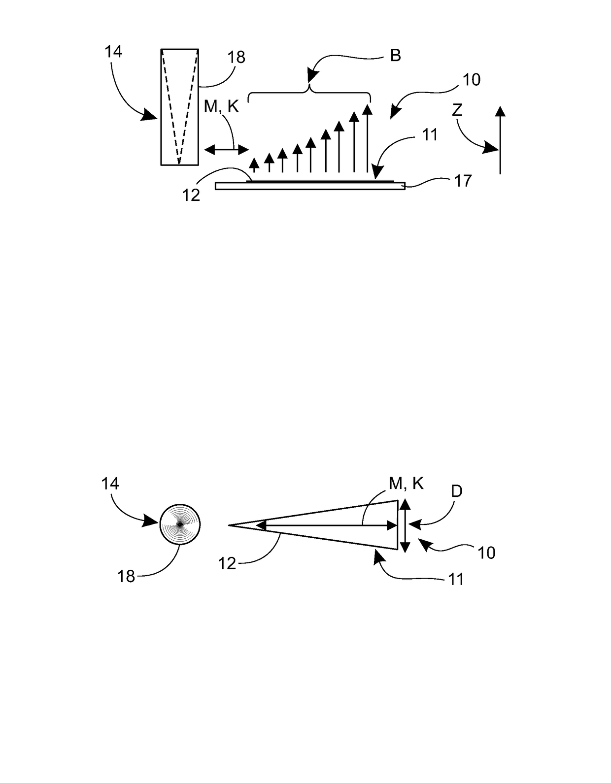
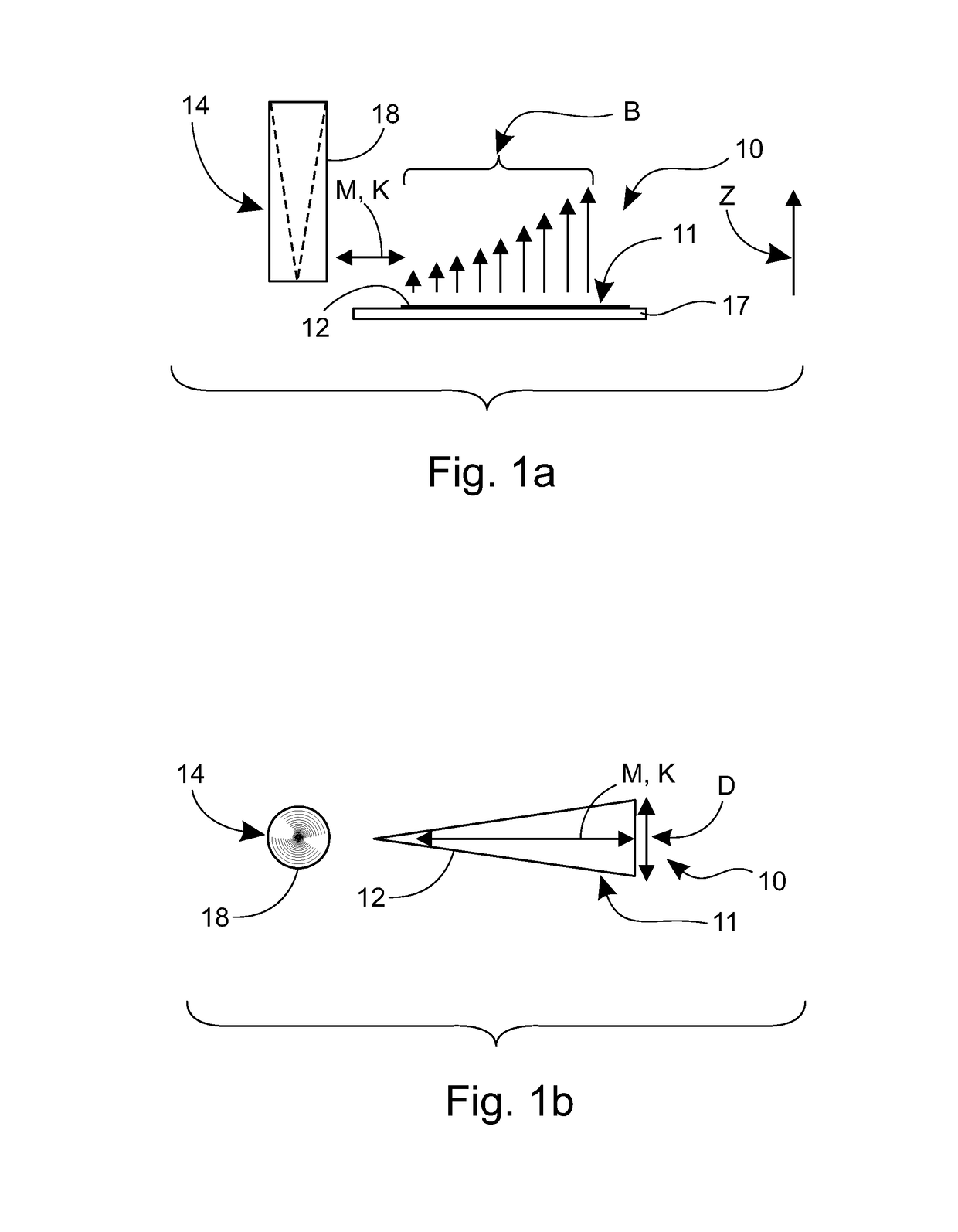
[0059]The total number of particles can also be measured without moving the sample, as described in the following embodiments. the total number of particles and the distribution of the particles in the sample can be determined, for example, by exploiting the non-linear distance dependence. In this case, it will thus be sufficient for the sample 14 to be brought, for example, from above into the area of effect of the coil 12 at one measurement point and for the signal level to be measured as the sample 14 approaches the coil 12 from different distances. The sample 14 thus does not move at all in the measurement direction shown by the reference M, but instead in the direction shown by the reference Z.

[0060]A second alternative to the determining of the total number of particles is the measurement of a mixed sample, in which case the particles are distributed evenly in the sample. Because the signal level is initially measured from this in a specific volume (in the measurement area of...

third embodiment

[0061] the number of particles can be measured from the settling time of the sample. If the sample is in liquid form, and its properties (including its viscosity) are known, these properties can be exploited to determine the number of particles. The large particles settle on the bottom more slowly than the smaller particles. If an estimate of the distribution is determined on the basis of the settling time, the impedance-measurement result can be used to estimate the total number of particles. By combining these results, the measurement accuracy is again improved.

[0062]In some cases, a change in the measurement frequency can also be exploited for determining the particle distribution. For example, when using electrically conductive samples, an increase in the measurement frequency reduces the penetration depth of the magnetic field, so that this can be exploited to some extent correspondingly to the change in the coil's geometry. If the size or structure of the clusters of super-par...


PUM

PropertyMeasurementUnit
width D2aaaaaaaaaa
width D2aaaaaaaaaa
width D2aaaaaaaaaa

Abstract

The invention relates to a measuring arrangement comprising: a coil arrangement for creating a magnetic field to measure a sample to be arranged in connection with it including at least one flat coil, the coil geometry of which is arranged to be changed in the direction of the plane defined by the coil arrangement, in order to create a spatially changing magnetic field having a known distance dependence for measuring the sample; and electronics connected to the coil arrangement for creating a magnetic field using the coil arrangement; and means for changing the position of the sample and the coil arrangement relative to each other in order to change the magnetic field affecting the sample and having the known distance dependence. In addition, the invention also relates to a method for measuring a sample.

Description

CROSS-REFERENCE TO RELATED APPLICATIONS[0001]This application is a U.S. National Stage Application of International Patent Application No. PCT / FI2015 / 050190, filed Mar. 20, 2015, which claims benefit of Finland Patent Application No. 20145267, filed Mar. 21, 2014.TECHNICAL FIELD[0002]The present invention relates to a measuring arrangement, which includes[0003]a coil arrangement arranged to create a magnetic field in order to measure a sample to be arranged in connection with it,[0004]electronics connected to the coil arrangement for creating a magnetic field using the coil arrangement.[0005]The invention also relates to a method for measuring a sample.BACKGROUND OF THE INVENTION[0006]Needs are known to analyse, for example, various samples, in which there are, for example, magnetic particles. The magnetic particles can either, for example, belong to the sample itself, and / or have been added to it for analysis. Generally, it can be said that the sample to be analysed includes substa...

Claims


Application Information

Patent Timeline
Patent Type & Authority Applications(United States)
IPC IPC(8): G01N27/74G01R33/12G01N27/02B03C1/033
CPCG01N27/745B03C1/0335B03C2201/18G01N27/023G01R33/1276G01N35/0098B03C1/288G01R33/0213G01N27/74G01R33/12
Inventor SAVONEN, MARKUS
Owner MAGNASENSE TECH OY
Learn More