
Thermal metal oxide varistor circuit protection device

a circuit protection device and metal oxide technology, applied in the direction of overvoltage protection resistors, emergency springs, relays, etc., can solve the problems of thermal link melting, delay in response times, and complicated assembly

Inactive Publication Date: 2017-04-20
LITTELFUSE INC
View PDF9 Cites 13 Cited by
  • Summary
  • Abstract
  • Description
  • Claims
  • Application Information

AI Technical Summary

Benefits of technology

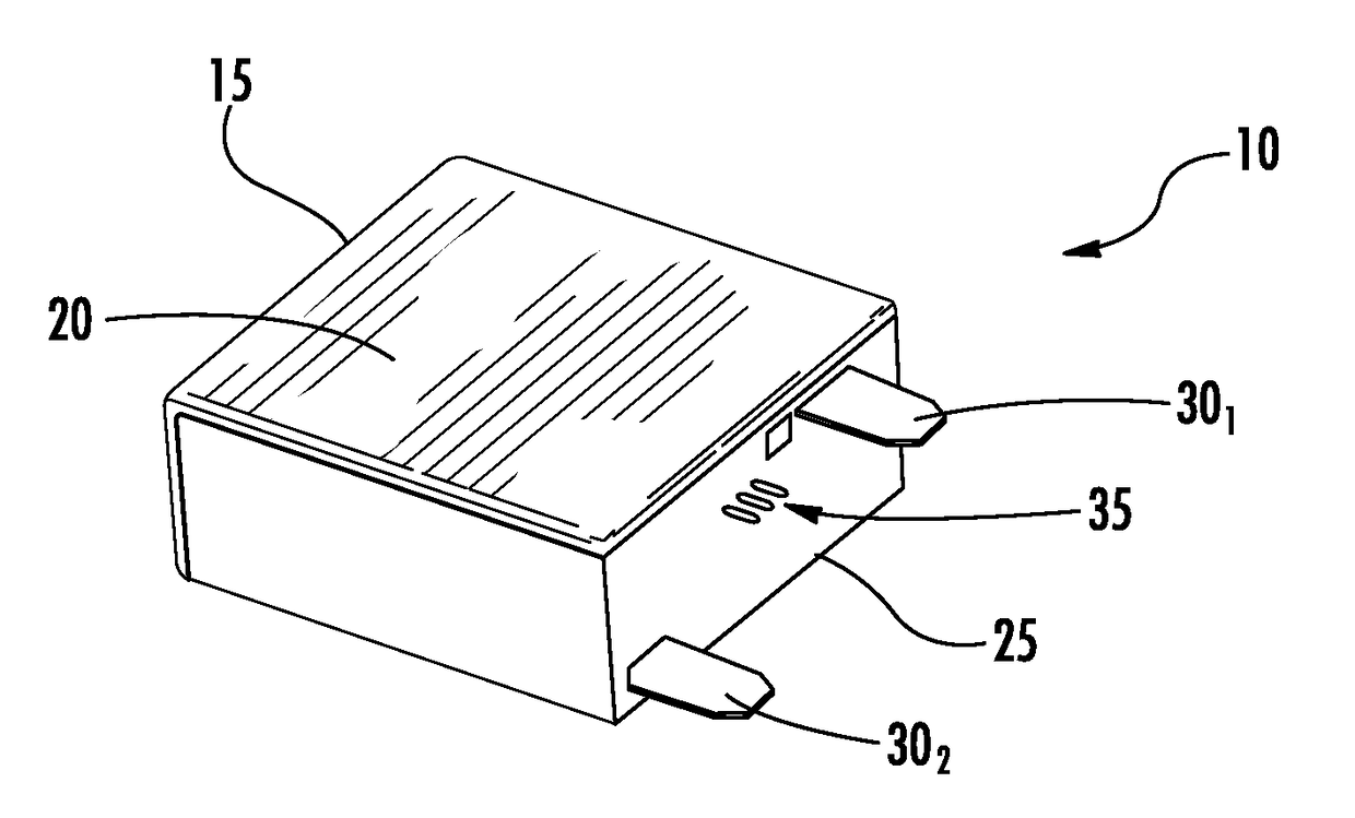
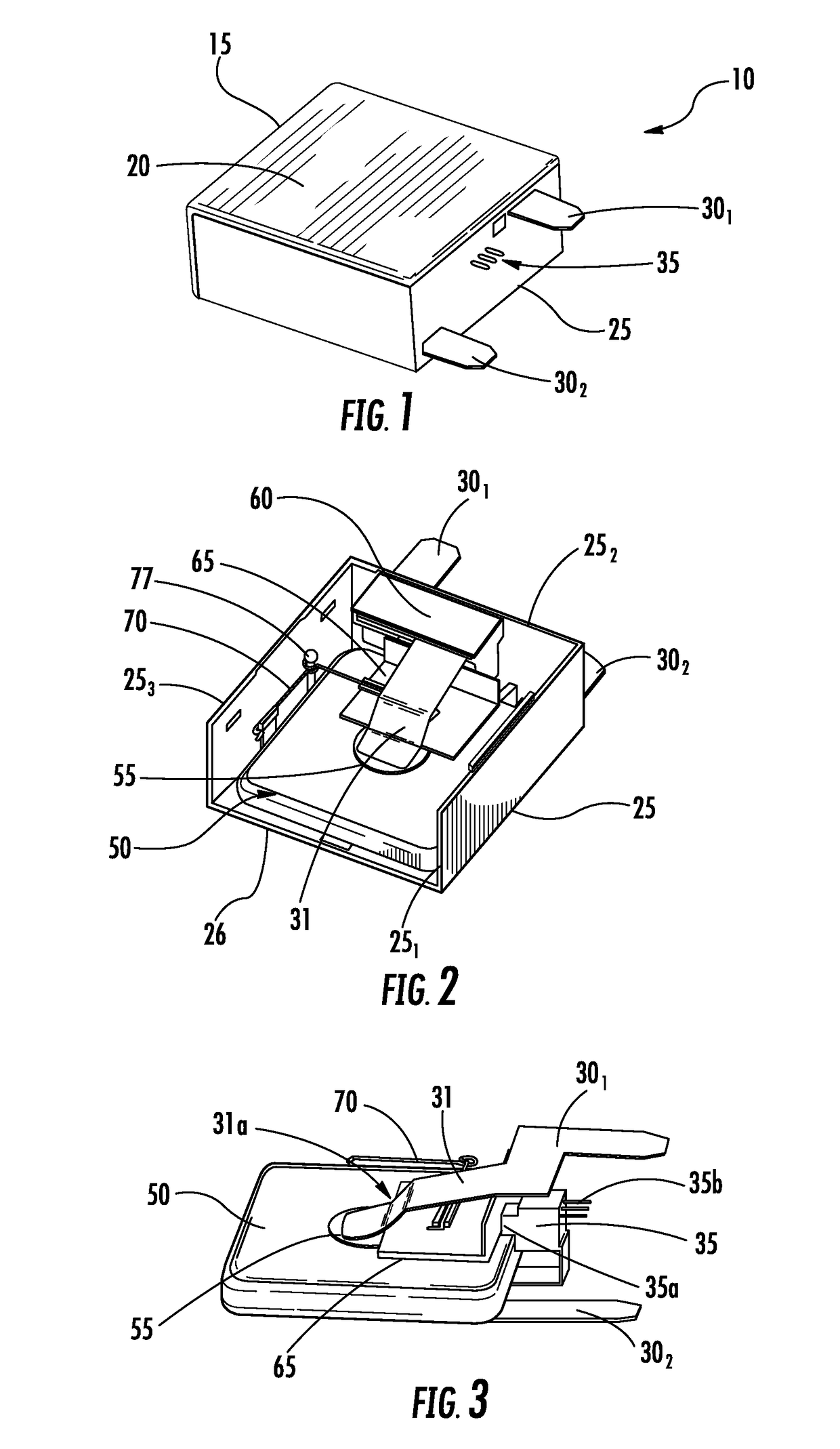
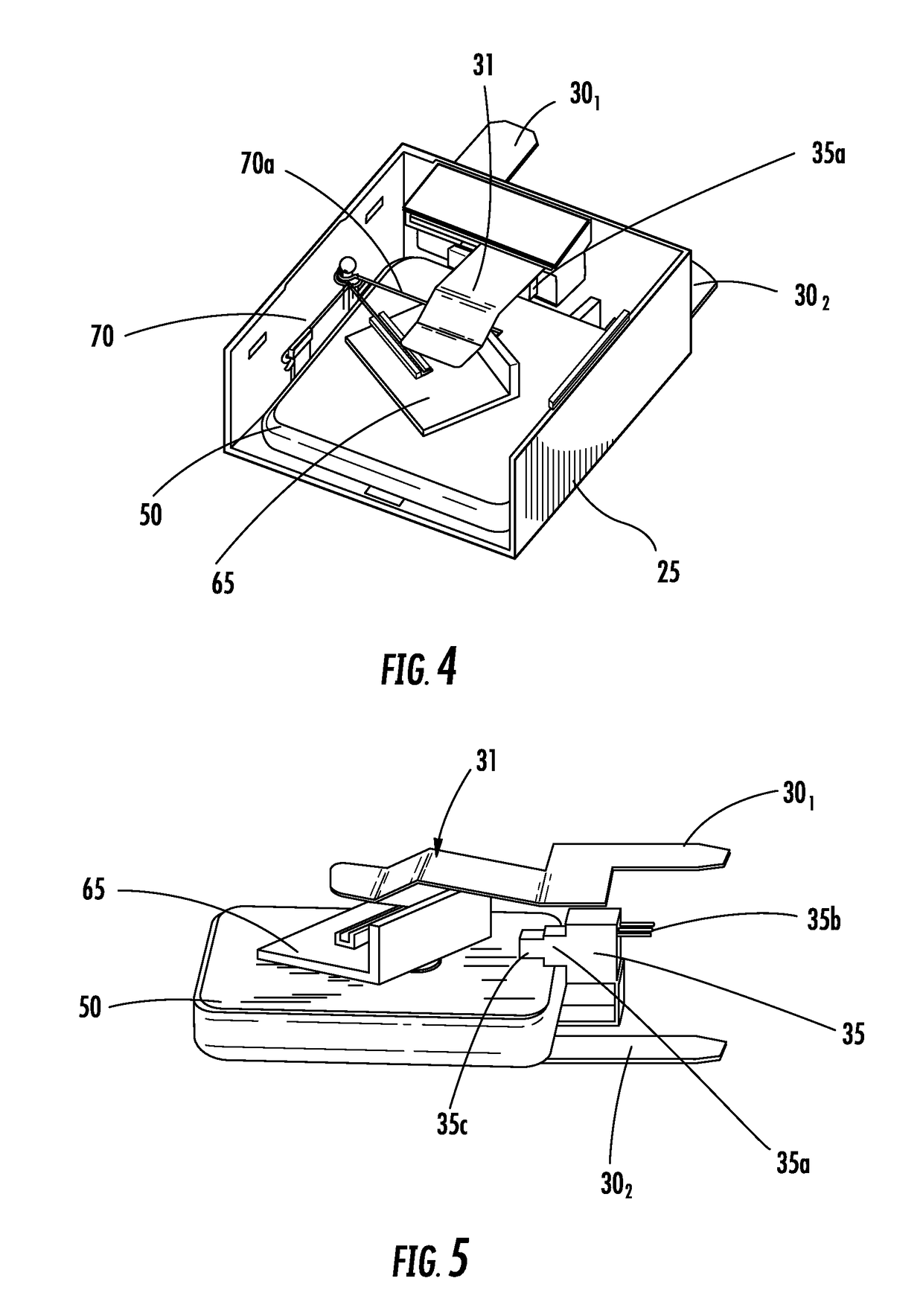
The patent text describes a circuit protection device that includes a metal oxide varistor (MOV) and a spring. When a voltage surge condition occurs, the MOV changes from a non-conductive state to a conductive state and current flows between two terminals. The heat generated by the current melts the solder and creates an open circuit. The device also includes a protrusion extending from the surface of the MOV and a micro switch with an indicator portion. The device is designed to protect sensitive components from voltage surges and ensure reliable operation.

Problems solved by technology

This causes the thermal link to melt.
However, these existing circuit protection devices do not provide an efficient heat transfer from the MOV to the thermal link, thereby delaying response times. In addition, existing circuit protection devices are complicated to assembly which increases manufacturing costs.

Method used


Image

  • Thermal metal oxide varistor circuit protection device
  • Thermal metal oxide varistor circuit protection device
  • Thermal metal oxide varistor circuit protection device

Examples


Embodiment Construction

[0019]The present invention will now be described more fully hereinafter with reference to the accompanying drawings, in which preferred embodiments of the invention are shown. This invention, however, may be embodied in many different forms and should not be construed as limited to the embodiments set forth herein. Rather, these embodiments are provided so that this disclosure will be thorough and complete, and will fully convey the scope of the invention to those skilled in the art. In the drawings, like numbers refer to like elements throughout.

[0020]In the following description and / or claims, the terms “on,”“overlying,”“disposed on” and “over” may be used in the following description and claims. “On,”“overlying,”“disposed on” and “over” may be used to indicate that two or more elements are in direct physical contact with each other. However, “on,”, “overlying,”“disposed on,” and over, may also mean that two or more elements are not in direct contact with each other. For example,...


PUM


Abstract

Exemplary embodiments of the present invention are directed to a circuit protection device, A circuit protection device may comprise a housing defining a cavity and a metal oxide varistor (MOV) disposed within the cavity. The circuit protection device may further comprise a first terminal electrically attached at a first end to the MOV by solder and extending outside of the housing at a second end. An arc shield is disposed within the housing between the first end of the first terminal and at least partially over the solder. The circuit protection device may further comprise a spring configured to bias the arc shield against a micro switch having an indicator portion disposed at least partially outside of the housing. When a voltage surge condition occurs, the MOV changes from a non-conductive state to a conductive state and current flows between the first terminal and a second terminal where the heat generated by the current flowing through the varistor melts the solder and the first end of the first terminal electrically separates from the varistor.

Description

RELATED APPLICATIONS[0001]This Application is a divisional of U.S. patent application Ser. No. 14 / 232,412, filed Jan. 13, 2014, which is a National Stage Entry of PCT / CN2011 / 075879, filed Jun. 17, 2011, and incorporated by reference herein in their entirety.BACKGROUND OF THE INVENTION[0002]Field of the Invention[0003]Embodiments of the invention relate to the field of circuit protection devices. More particularly, the present invention relates to a surge protection device with a thermal disconnect system configured to provide fist response to overheating,[0004]Discussion of Related Art[0005]Over-voltage protection devices are used to protect electronic circuits and components from damage due to over-voltage fault conditions. These over-voltage protection devices may include metal oxide varistors (MOVs) that are connected between the circuits to be protected and a ground line. MOVs have a unique current-voltage characteristic that allows them to be used to protect such circuits again...

Claims


Application Information

Patent Timeline
Patent Type & Authority Applications(United States)
IPC IPC(8): H01H85/02H01C1/14H01H85/04H01C7/112H01C7/12
CPCH01H85/0241H01C7/112H01H2235/00H01H85/04H01C1/14H01C7/12H01C7/102H01C7/126H01H2037/762H01H37/761H01H9/32H01C7/10H01H61/02
Inventor YANG, WENTANG, HAILANGLIU, HONGBING
Owner LITTELFUSE INC
Learn More