Cable assembly, connector, and method for manufacturing cable assembly

a technology of cable assembly and connector, which is applied in the direction of cables, insulated conductors, coupling device connections, etc., can solve the problems of deteriorating positioning precision of the swaged portion, and achieve the effect of reducing load and improving resistance to water and dus

Active Publication Date: 2017-04-20
HOSIDEN CORP
View PDF17 Cites 17 Cited by
  • Summary
  • Abstract
  • Description
  • Claims
  • Application Information

AI Technical Summary

Benefits of technology

[0016]The second unswaged portion may include an inner rim on the other side in the first direction of the second unswaged portion, and a chamfer along the inner rim. In the cable assembly of this aspect, the chamfer is provided along the inner rim to reduce the possibility that the outer insulator of the cable is brought into contact with the inner rim of the second unswaged portion even when the cable is bent on the other side in the first direction of the metal case. Such reduced contacts reduces load onto the outer insulator of the cable.
[0017]The second unswaged portion may have a housing recess of ring shape. The housing recess may communicate with a hole of the second unswaged portion and have a bottom. The cable assembly of any aspect described above may further include a first seal being an annular elastic body housed in the housing recess. The outer insulator of the cable may extend through the first seal. The first seal may be in intimate contact with the outer insulator and the bottom of the housing recess. The cable assembly of this aspect has improved resistance to water and dust.

Problems solved by technology

In the wrapping process, the swaged portion may be fixed to the outer insulator of the coaxial cable and the connecting portion of the coaxial connector at a wrong position different from a predetermined position, resulting in deteriorated positioning precision of the swaged portion.

Method used


Image

  • Cable assembly, connector, and method for manufacturing cable assembly
  • Cable assembly, connector, and method for manufacturing cable assembly
  • Cable assembly, connector, and method for manufacturing cable assembly

Examples


Embodiment Construction

[0040]Embodiments of the invention will be described below.

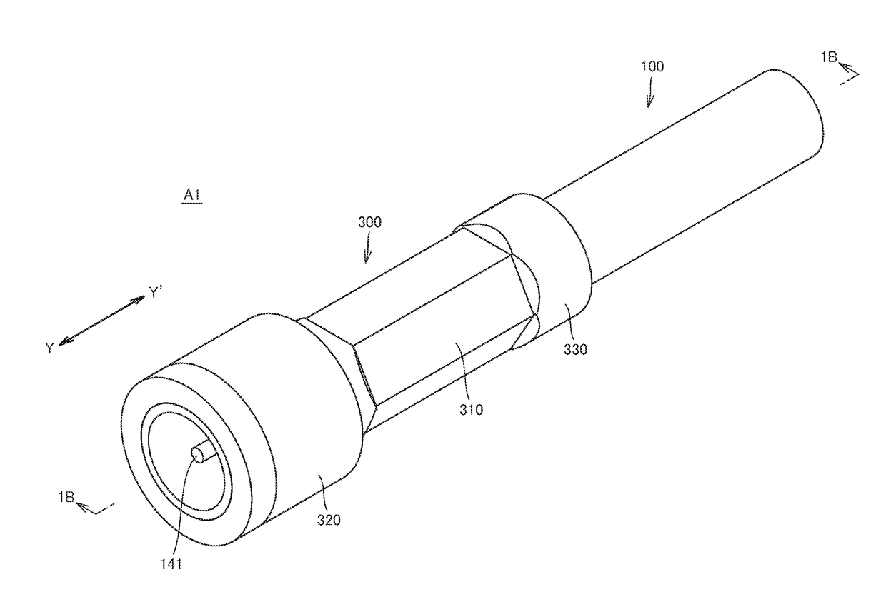
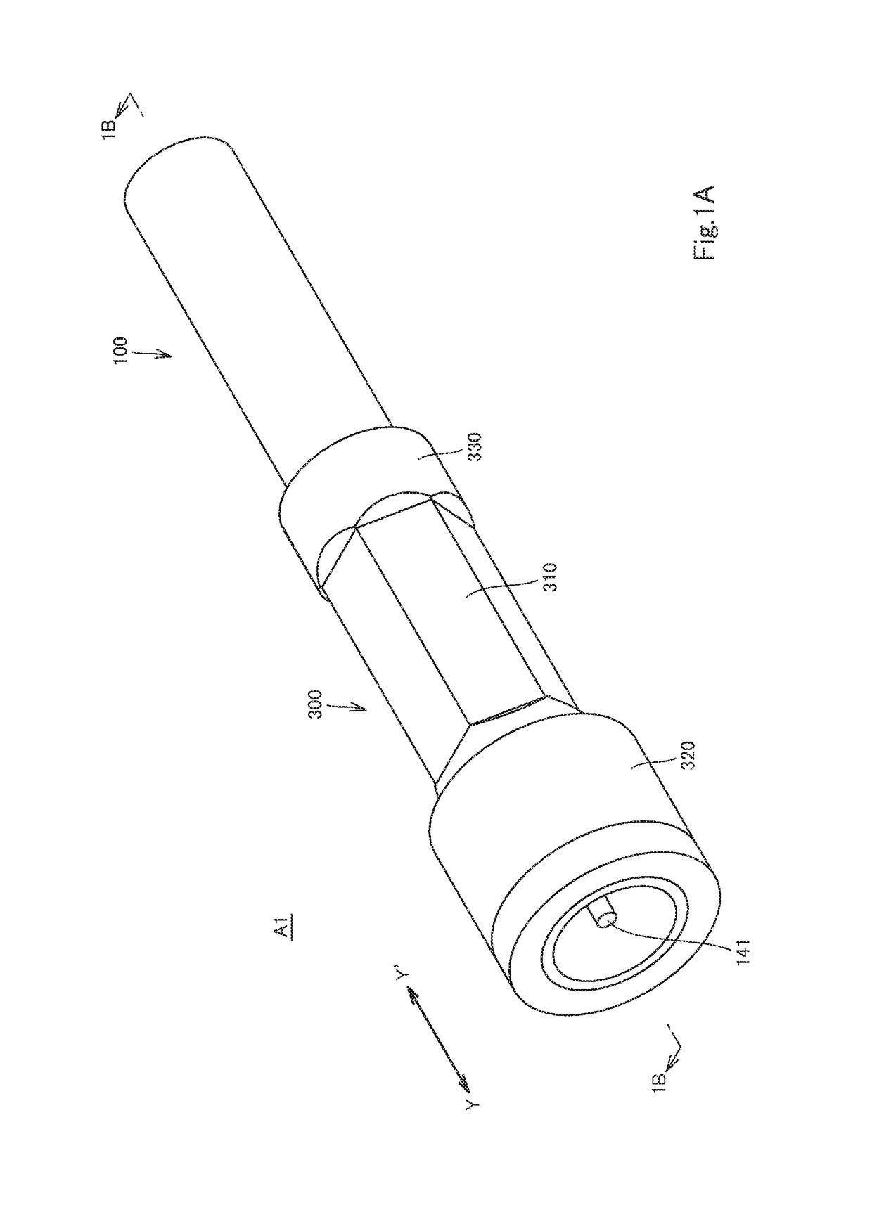
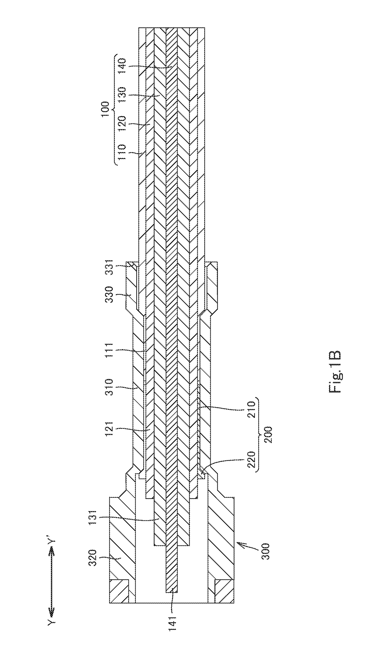
[0041]A cable assembly A1 (hereinafter also referred to as assembly A1) according to some embodiments of the invention will now be described with reference to FIGS. 1A to 2B. FIGS. 1A to 2B show an assembly A1 according to one of the embodiments (hereinafter referred to as the first embodiment). The assembly A1 includes a cable 100, a clamp 200 made of metal, and a metal case 300 of tuboid shape. FIG. 1A and FIG. 1B indicate the Y-Y′ direction, which corresponds to the longitudinal direction of the metal case 300 and the first direction in the claim. In the Y-Y′ direction, the Y direction corresponds to one side in the first direction, and the Y′ direction corresponds to the other side in the first direction.

[0042]The cable 100 includes an outer insulator 110 of tuboid shape, an outer conductor 120 of tuboid shape, at least one inner insulator 130 of tuboid shape, and at least one inner conductor 140. The outer insulator 110...


PUM

PropertyMeasurementUnit
shapeaaaaaaaaaa
pressureaaaaaaaaaa
inner sizeaaaaaaaaaa

Abstract

A cable assembly including a cable, a metal clamp, and a tuboid metal case. The cable includes a outer insulator and a outer conductor thereinside. The outer conductor includes a protruding portion protruding to one side in the first direction from an end portion of the outer insulator on the one side in the first direction. The clamp holds the protruding portion and includes an end portion on the other side in the first direction. The metal case includes a swaged portion, which houses at least the end portion of the outer insulator and the end portion of the clamp. Swaged from outside, the swaged portion is in pressure contact with and fixed to at least the end portion of the outer insulator and the end portion of the clamp so that the end portion of the outer insulator is elastically deformed and the end portion of the clamp is plastically deformed.

Description

CROSS-REFERENCE TO RELATED APPLICATIONS[0001]The present application claims priority under 35 U.S.C. §119 of Japanese Patent Application No. 2015-206128 filed on Oct. 20, 2015, the disclosure of which is expressly incorporated by reference herein in its entity.BACKGROUND OF THE INVENTION[0002]Technical Field[0003]The invention relates to cable assemblies, connectors, and methods for manufacturing the cable assemblies.[0004]Background Art[0005]Unexamined Japanese Patent Application Publication No. 05-217638 discloses a structure of a coaxial cable mounted to a coaxial connector. This conventional structure includes a coaxial connector, a coaxial cable, and a swaged portion.[0006]The coaxial connector has a metal shell, a socket, and an insulative body. The metal shell has a main portion and a tuboid connecting portion. The main portion of the metal shell houses the socket and the body holding the socket.[0007]The coaxial cable has a tuboid outer insulator, a tuboid shield conductor i...

Claims


Application Information

Patent Timeline
Patent Type & Authority Applications(United States)
IPC IPC(8): H01R24/38H01B7/20H01B11/18
CPCH01R24/38H01R2103/00H01B7/20H01B11/18H01R4/56H01R9/0524H01R13/502H01R4/20H01R9/0518H01R13/5205H01R43/16H01R13/5808
Inventor SASAKI, DAISUKE
Owner HOSIDEN CORP
Why Eureka
Try Eureka