Well re-stimulation

a well and restimulation technology, applied in the field of well restimulation, can solve the problems of unrealistic use of sophisticated completion systems, excessive horsepower, and/or excessive sand,

Inactive Publication Date: 2017-04-27
SCHLUMBERGER TECH CORP
View PDF2 Cites 123 Cited by
  • Summary
  • Abstract
  • Description
  • Claims
  • Application Information

AI Technical Summary

Benefits of technology

[0008]In some embodiments, pore pressure and cluster stresses are optionally determined at a start of the treatment, and goal ISIPs, corresponding to undepleted regions of the formation, and target ISIPs versus treatment progression or stage, beginning with the depleted regions, are developed. In some embodiments, the diversion and proppant pumping schedules are designed, based on different levels of available information and simulating tools, and the refracturing treatment is initiated accordingly. If the ISIP at the end of a stage varies appreciably from the design, then subsequent stages may be modified to more closely match the designed ISIP schedule.

Problems solved by technology

However, the stage design for refracs applying diversion techniques remains as a considerable challenge to the industry, which must meet at least two criteria.
The second criterion is that the overall treatment cost must respect the economic constraints and be proportional to the production improvement, viz., it is not realistic to use sophisticated completion systems, excessive amounts of sand, fracturing fluid additives, or other stimulating material, and / or excessive horsepower, i.e., an unrealistic number of fracturing pumps.

Method used


Image

  • Well re-stimulation
  • Well re-stimulation
  • Well re-stimulation

Examples


embodiments listing

[0122]In some aspects, the disclosure herein relates generally to well re-stimulation methods and / or workflow processes according to the following Embodiments, among others:

embodiment 1

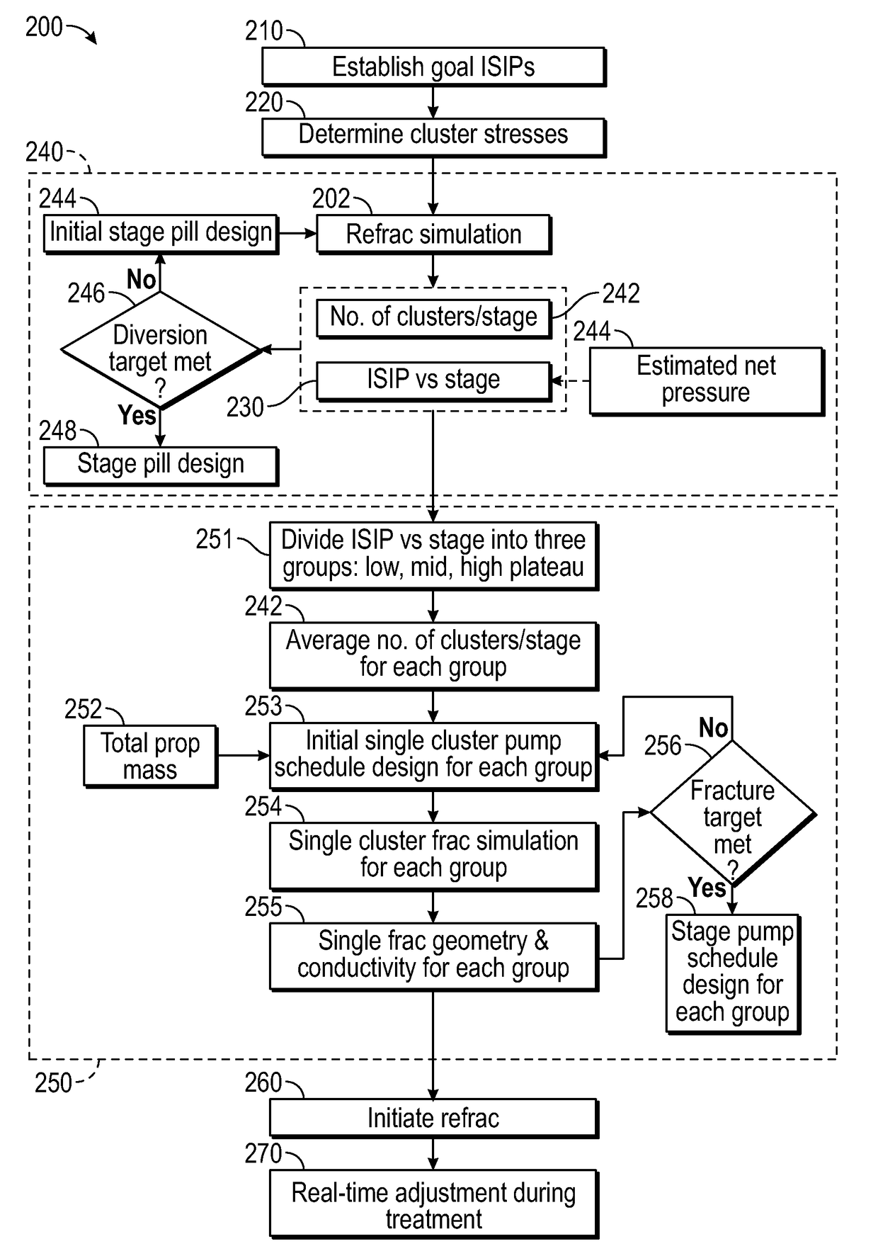
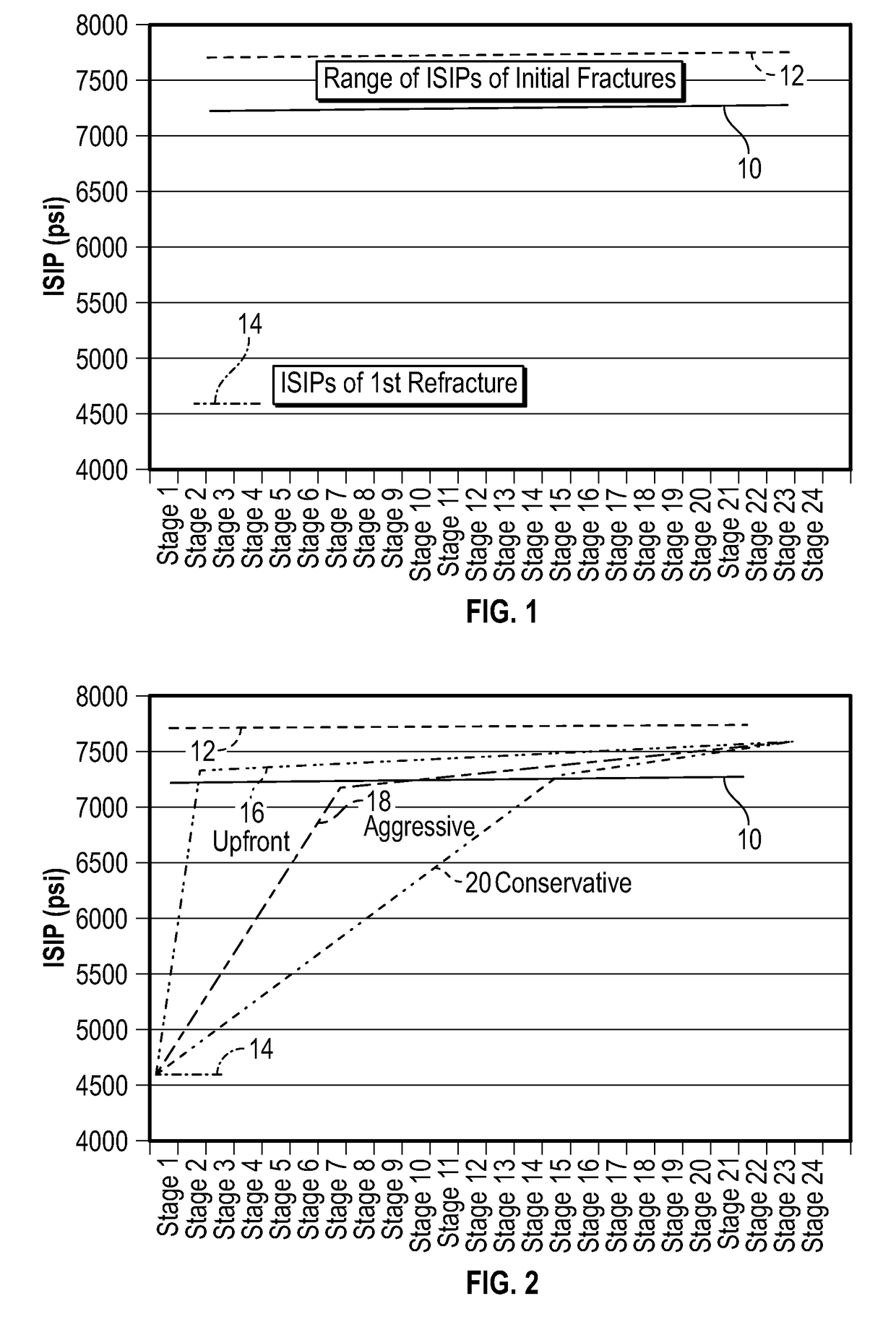
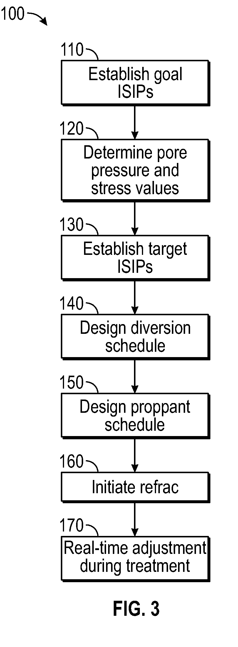
[0123]A method for re-stimulation treatment of a well penetrating a formation, comprising: (a) establishing a goal range of instantaneous shut-in pressure (ISIP) values for refracturing treatment of a well having pre-existing fractures from a previous stimulation, wherein the goal range comprises minimum and maximum ISIP values corresponding to undepleted regions of the formation; (b) determining pore pressure and cluster stresses along the well at a start of the re-stimulation treatment; (c) establishing target ISIP values versus treatment progression, wherein the target ISIP values comprise a minimum target ISIP value equal to or greater than a lowest pore pressure in the formation at a start of the re-stimulation treatment corresponding to depleted regions of the formation, and a maximum target ISIP value within the goal range of ISIP values at an end of the re-stimulation treatment corresponding to the undepleted regions; (d) designing a diversion schedule for a number of stages...

embodiment 2

[0124]the method of Embodiment 1, wherein (d) comprises simulating the refracturing treatment to determine a number of clusters for fracture initiation for the diversion pill in the respective stages, to determine a minimum cluster stress for the respective stages, and to calculate the ISIP for the respective stages as a function of the determined minimum cluster stress; comparing the calculated ISIP with the target ISIP value to obtain a difference; if the difference is greater than a predetermined amount, modifying the diversion schedule and repeating the refracturing treatment simulation; and repeating the comparison and the modification until the difference is less than the predetermined amount.


PUM


Abstract

Method for well re-stimulation treatment using instantaneous shut-in pressure (ISIP) to guide the design and execution of refracturing stages. Pore pressure and optional cluster stresses are determined at a start of the treatment. Goal ISIPs for the refracturing correspond to undepleted regions of the formation, and target ISIPs versus treatment progression/stage range from about a lowest pore pressure corresponding to depleted regions of the formation up to within the goal range ISIPs. Diversion and proppant pumping schedules are designed, and the refracturing treatment is initiated in accordance with the design. ISIP is measured at stage end, and if it varies from the target ISIP, subsequent stages are modified from the design as needed to more closely match the ISIP schedule.

Description

CROSS REFERENCE TO RELATED APPLICATION(S)[0001]None.BACKGROUND[0002]A refracturing treatment, which is sometimes also called a “refrac”, is the operation for stimulating a well which has a history of previous stimulation by fracturing. Often, a refrac is motivated by a level of production that has declined, usually to or below an economic limit. In some cases, a refrac may boost production to a higher level and make the well economic again.[0003]Well re-stimulation treatments usually involve a well with pre-existing perforations as well as new perforations that may be added as a part of the re-stimulation treatment. There is usually no hydraulic isolation device inside the wellbore. Diversion techniques, such as, for example, BROADBAND SEQUENCE™ treatment and / or the diverters disclosed in U.S. Pat. No. 7,036,587, U.S. Pat. No. 7,267,170, and U.S. Pat. No. 8,905,133, enable multistage fracturing treatment without using isolation devices inside the wellbore. However, the stage design ...

Claims


Application Information

Patent Timeline
Patent Type & Authority Applications(United States)
IPC IPC(8): E21B41/00G01V99/00E21B49/00E21B43/26E21B43/267
CPCE21B41/0092E21B43/26G01V99/005E21B49/00E21B49/008E21B43/267G06Q10/06
Inventor LECERF, BRUNOCLARK, BRIAN D.GU, HONGRENUSOLTSEV, DMITRIYMALPANI, RAJGOPAL V.SINOSIC, BRIAN
Owner SCHLUMBERGER TECH CORP
Why Eureka
Try Eureka