Heat dissipation structure and water block having the same

Inactive Publication Date: 2017-04-27
TAIWAN MICROLOOPS CORP
View PDF9 Cites 10 Cited by
  • Summary
  • Abstract
  • Description
  • Claims
  • Application Information

AI Technical Summary

Benefits of technology

[0010]The present disclosure further achieves the following effect. The basal segments are able to be made significantly thinner, thermal resistances thereof are therefore reduced, and heat could be rapidly transfer

Problems solved by technology

However, the aforementioned heat dissipation structures perform poor thermal conductivity and are complicated for manufacture.
The heat dissipation structure possesses good thermal conductivity, but is poor.
However, there are following problems in actual use.
Each case of the vapor chamber resist

Method used


Image

  • Heat dissipation structure and water block having the same
  • Heat dissipation structure and water block having the same
  • Heat dissipation structure and water block having the same

Examples


Embodiment Construction

[0019]Detail descriptions and technical contents of the present disclosure are described below with drawings. However, the drawings are provided for reference and demonstration, and the present disclosure should not be limited by the drawings.

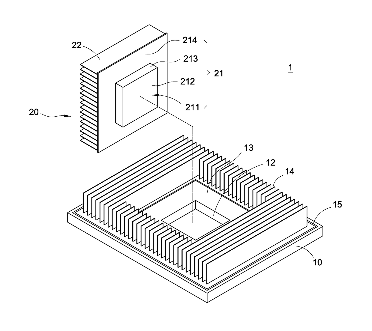
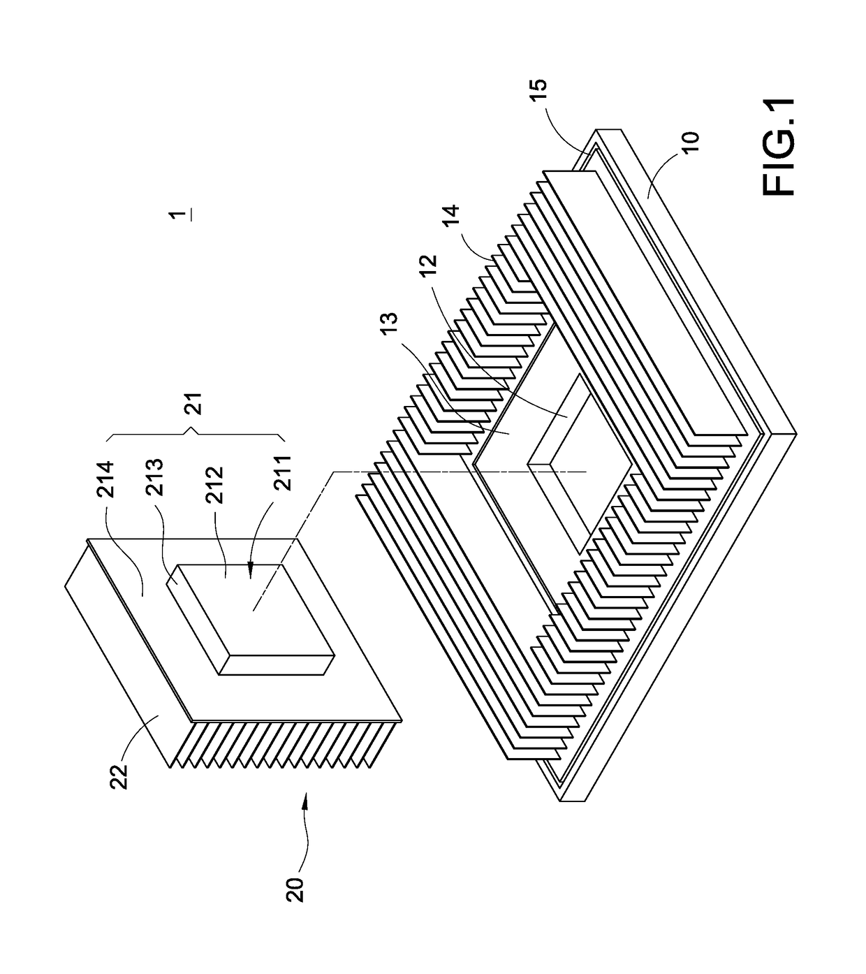
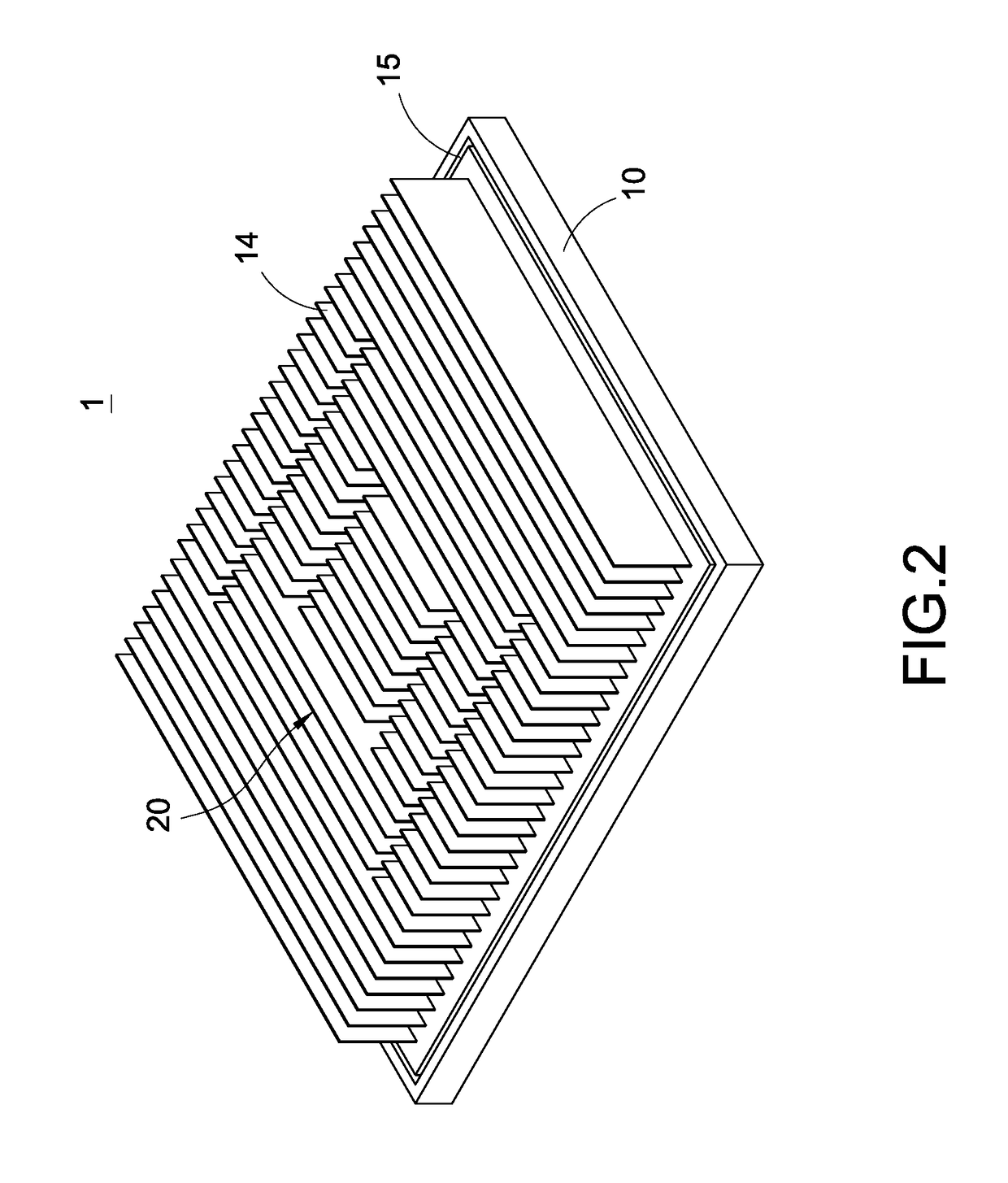
[0020]Please refer to FIG. 1 to FIG. 3. A heat dissipation structure 1 is provided in the present disclosure. The heat dissipation structure primarily comprises a vapor chamber 10 and a heat dissipation component 20.

[0021]A vacuum chamber is formed in the vapor chamber 10. Capillaries made with meshes and sintered metals and supporters constituted by helical springs or rods are disposed in the vacuum chamber. Working fluid such as water is filled in the vacuum chamber. Heat is transferred by the working fluid via vapor-liquid phase change. The vapor chamber 10 of the present embodiment is substantially a rectangular body, but shapes thereof should not be limited thereby. The vapor chamber 10 could also be a cylinder or another shapes. A heated ...


PUM


Abstract

A heat dissipation structure and water block having the same are provided in the present disclosure. The heat dissipation structure includes a vapor chamber and a heat dissipation component. A through opening is disposed on and through the vapor chamber, and the vapor chamber includes a heated surface. The heat dissipation component includes a base plate and multiple fins extended from the base plate, and the base plate includes a bottom surface. The heat dissipation component is configured corresponding to the through opening, and a coplanar structure is formed by the bottom surface and the heated surface. Heat conductive and heat dissipation performances of the heat dissipation structure and the water block are thereby improved.

Description

BACKGROUND OF THE INVENTION[0001]Technical Field[0002]The present disclosure is related to heat dissipation technology, and particularly related to a heat dissipation structure and water block having the same applied on heat generating electronic element.[0003]Description of Prior Art[0004]Heat generated by electronic components is increased as operation speed thereof rising. Heat dissipation devices or vapor chambers made of alloy of aluminum and copper are commonly applied to effectively solve the problem of high heat generation. However, the aforementioned heat dissipation structures perform poor thermal conductivity and are complicated for manufacture.[0005]A conventional heat dissipation device comprises a base plate and fins extended from the base plate. The heat dissipation structure possesses good thermal conductivity, but is poor. Therefore, heat dissipation structures including the vapor chamber and the heat dissipation device are developed. The heat dissipation device is ...

Claims


Application Information

Patent Timeline
IPC IPC(8): F28D15/02F28D15/04H05K7/20
CPCF28D15/0275F28D15/04H05K7/20309F28F3/02F28D15/0233H01L23/3672H01L23/427H01L23/473H01L2023/4056
Inventor LIN, CHUN-HUNG
Owner TAIWAN MICROLOOPS CORP
Why Eureka
Try Eureka