Thermal Monitoring of Battery Packs

a battery pack and health monitoring technology, applied in the direction of thermometers, safety/protection circuits, instruments, etc., can solve the problems of safety risk, affecting neighboring cells, and cascading failures

Inactive Publication Date: 2017-04-27
OXFORDIAN
View PDF7 Cites 35 Cited by
  • Summary
  • Abstract
  • Description
  • Claims
  • Application Information

AI Technical Summary

Problems solved by technology

Each battery pack type may exhibit different failure mechanisms under a variety of operating conditions; however, thermal abuse can damage any type of battery pack and lead to a safety risk.
If a cell is mechanically damaged, overcharged, over-discharged, charged or discharged at a high rate, exposed to excessive heat, or externally short circuited, or if it develops an internal short circuit, it can vent, explode, or catch fire, affecting neighboring cells and possibly leading to cascading failures.
In addition, the battery performance and cycle life are impacted by the operating temperature of the battery [1].
If a battery is operating at low temperatures, it may experience reduced performance.
Additionally, in the case of lithium-ion batteries, dendritic structures can form, resulting in internal short circuits.
This could lead to thermal runaway if undetected.
The cell's temperature could be elevated; however, due to a cold ambient environment, where a simple thermal strategy may initially fail to detect conditions leading up to thermal runaway.
Battery packs consisting of multiple cells with air-gaps or filler material may exhibit complex thermal profiles.
Physics-based models can be useful tools for battery cell designers; however, the solution of the coupled partial differential equations describing battery behavior is time-consuming [2] and thus difficult to use in real time for a BMS.
Whether simulating thermal runaway or the thermal profile within a battery pack experiencing typical usage conditions, the models are limited to offline use rather than within a BMS.
; however, they can add to the cost, weight, and complexity of the battery pack and are susceptible to failure themselves.
In large battery packs, sub-optimal placement of temperature sensors could delay the detection of a thermal event.
The presence of thermal sensors alone does not provide adequate safety for a battery pack.
However, this method does not discuss an approach to optimal sensor placement or the number of sensors optimally needed to estimate temperature distributions.

Method used


Image

  • Thermal Monitoring of Battery Packs
  • Thermal Monitoring of Battery Packs
  • Thermal Monitoring of Battery Packs

Examples


Embodiment Construction

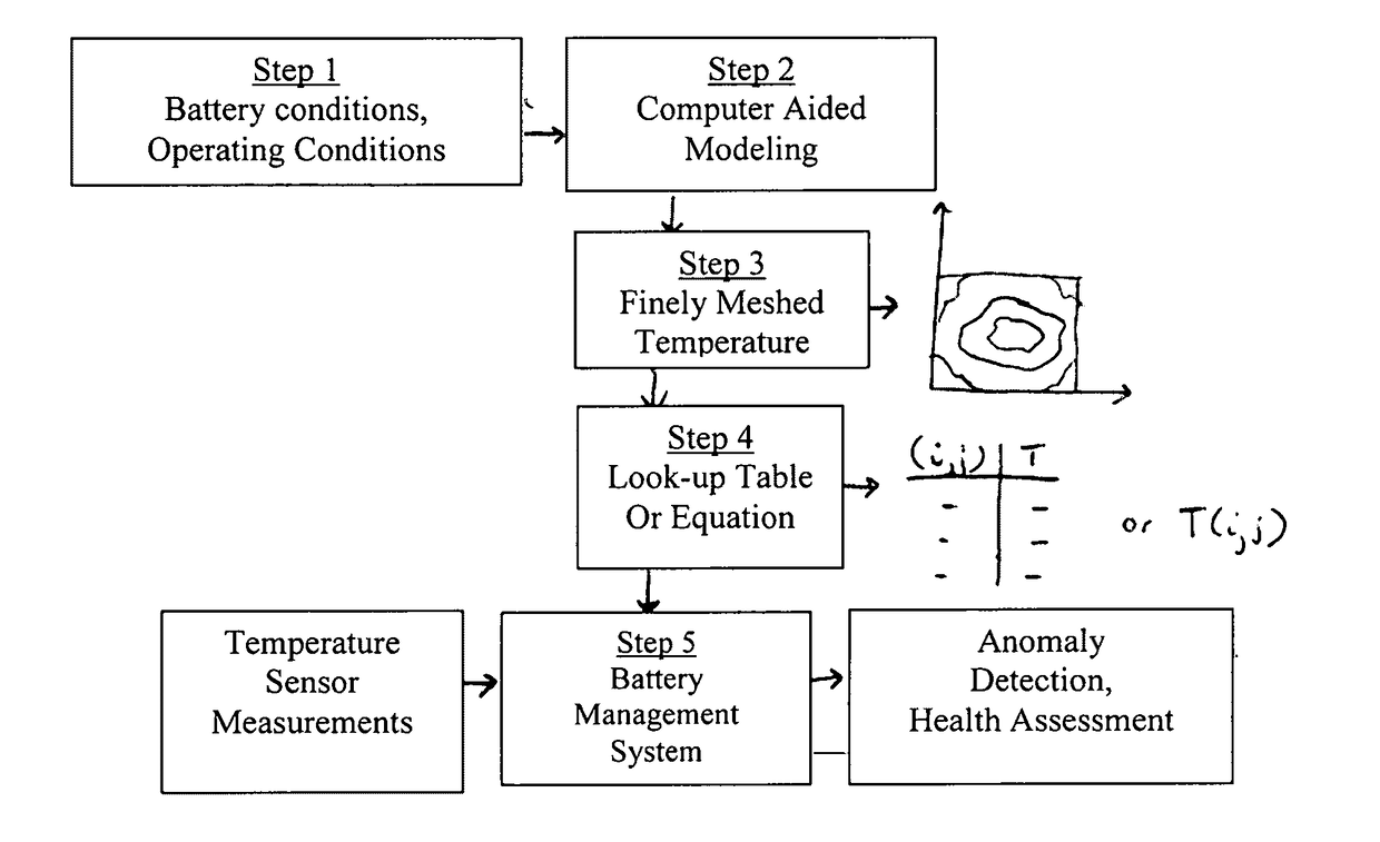
[0023]Temperature monitoring and modeling are not limited to anomaly detection and safety. This same strategy can be used for many purposes including, but not limited to, the design of control strategies, implementation of active thermal management, assessment of the remaining useful life of the battery, or determination of warranty coverage.

[0024]A general example of the embodiments of the invention is described below with reference to the accompanying drawings. The invention is not limited to the construction set forth and may take on many forms embodied as both hardware and / or software. The invention may be embodied as an apparatus, a system, a method, or a computer program. The numbers are used to refer to elements in the drawings.

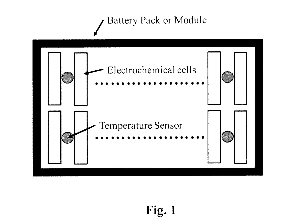
[0025]A battery pack is composed of at least one or more cells connected in various series and parallel combinations, such as shown in FIGS. 4A and 4B. In some embodiments individual cells are in the form of flat plate-like structures, which can be sta...


PUM

PropertyMeasurementUnit
temperaturesaaaaaaaaaa
temperatureaaaaaaaaaa
temperaturesaaaaaaaaaa

Abstract

A computer-aided health monitoring method is described for thermal monitoring of a battery pack that consists of using modeling to determine temperature distributions representative of safe battery operating conditions and a technique is described for comparing sensor measurements to a look-up table of the pre-modeled temperature profiles under various operating conditions. In one embodiment a simplified model of temperature distribution is described.

Description

FIELD OF INVENTION[0001]The present invention relates to health monitoring of a battery pack by assessing the operational temperatures of the pack with respect to expected thermal profiles. In some embodiments the battery pack includes integrated thermal sensors for determining the thermal profile of the battery pack at any given ambient temperature, and then comparing the measured profile to thermal profiles stored in the memory of a battery management system, said thermal profiles established under varying ambient temperature conditions either empirically or through a fully simulated design of experiments. An alert is issued when an excursion from normal is detected.BACKGROUND OF THE INVENTION[0002]A battery system describes a host device, its battery pack(s), and any other components used to support the operation of the device. The battery pack(s) can be used for primary or backup power for stationary or nonstationary applications. The battery types in common use today include bu...

Claims


Application Information

Patent Timeline
Patent Type & Authority Applications(United States)
IPC IPC(8): H02J7/00G01K3/14G01R31/36G01K1/02
CPCH02J7/0026G01R31/3675G01K3/14G01K1/026G01K2213/00H01M10/486H02J7/0029H01M2010/4271H01M10/633G01R31/374Y02E60/10
Inventor HENDRICKS, CHRISTOPHERPECHT, MICHAEL G.TOURANI, ABBAS
Owner OXFORDIAN
Why Eureka
Try Eureka