
Distributed firewalls and virtual network services using network packets with security tags

a network packet and security tag technology, applied in the field of firewalls, can solve the problems of over-inflated infrastructure, and inability to protect computers on a local area network from internal threats

Inactive Publication Date: 2017-04-27
ATTALA SYST LLC
View PDF8 Cites 111 Cited by
  • Summary
  • Abstract
  • Description
  • Claims
  • Application Information

AI Technical Summary

Benefits of technology

The invention provides a method for a distributed firewall and virtual network services on a network. It involves storing predefined security groups with rules for filtering network packets between virtual machines. Each virtual machine is assigned to one or more security groups. The method also includes filtering outgoing network packets based on the security rules associated with the sender's security group. The secured network packet is then transmitted into the network for delivery to the receiver. The technical effect of the invention is improved security and protection of virtual machines within a network.

Problems solved by technology

Conventional firewalls do not protect local area networks from internal attacks.
Accordingly, the traditional firewall at the entry point does not filter internal computer communication traffic and thus cannot protect computers on a local area network from an internal threat.
However, such an infrastructure is overly expensive.
Moreover, different policies are often applied to each of the firewalls, thereby increasing the complexity of administration and the load of filtering packets within the network.
However, each software firewall also requires tedious configuration as to the type of packets, or software application that is going to be used.
Protecting each and every computer server in a data center, including virtual servers, further complicates matters with regards to software firewalls.
Furthermore, setting up each and every software firewall for each and every computer server in a data center is rather tedious.
Additionally, software firewalls tend to become network bottlenecks.
Due to the increasing speed of networks, amount of data passing through, and the complexity of protocols that firewalls must support, software firewalls are more likely to be the congestion points of networks.

Method used


Image

  • Distributed firewalls and virtual network services using network packets with security tags
  • Distributed firewalls and virtual network services using network packets with security tags
  • Distributed firewalls and virtual network services using network packets with security tags

Examples


Embodiment Construction

[0027]In the following detailed description of the embodiments of the invention, numerous specific details are set forth in order to provide a thorough understanding of the present invention. However, it will be understood by one skilled in the art that the embodiments of the invention may be practiced without these specific details. In other instances well-known methods, procedures, components, and circuits have not been described in detail so as not to obscure aspects of the embodiments of the invention unnecessarily.

[0028]The embodiments of the invention include a method, apparatus, and system for distributed firewalls and virtual network services.

Distributed Firewalls

[0029]The method operates in distributed firewalls in a virtualized server environment. An overview of firewalls, access control rules and virtualization are presented in the following sections before presenting the method of the present technology.

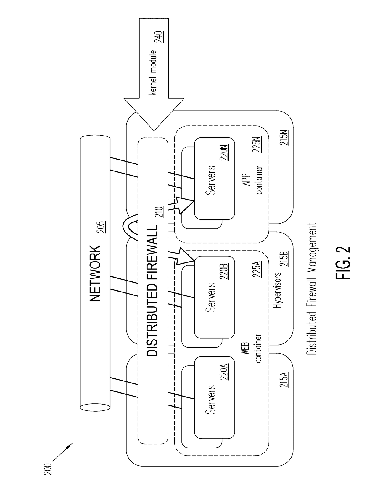
[0030]FIG. 2 is a conceptual diagram of a network 200 that includes ...


PUM


Abstract

A method, system, and apparatus are provided for a distributed firewall and virtual network services on a network. In one example, the method includes storing a plurality of predefined security groups, wherein each predefined security group has a set of predefined security rules for network packets configured to be transmitted between virtual machines (VMs) within the network; associating each virtual machine (VM) within the network with one or more predefined security groups (SGs); filtering an outgoing network packet from a sending VM to a receiving VM in response to the predefined security rules associated with the predefined SGs associated with the sending VM to validate the communication desired in the outgoing network packet; forming a secured network packet by encapsulating a header, a security tag, and the outgoing network packet together; and transmitting the secured network packet into the network for delivery to the receiving VM.

Description

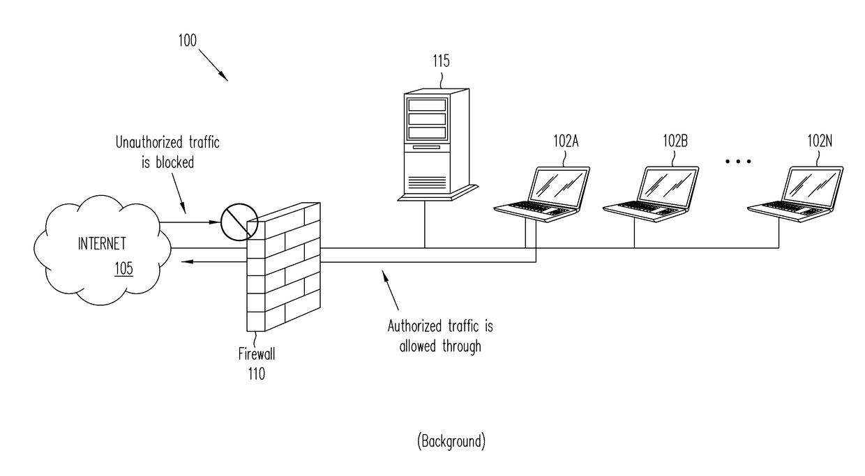
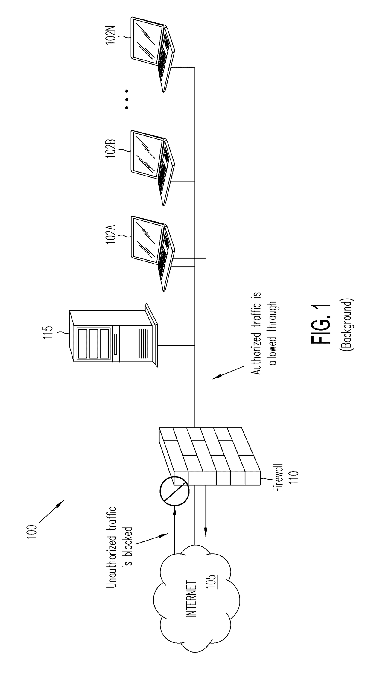
FIELD[0001]The embodiments of the invention relate generally to firewalls.BACKGROUND[0002]A conventional firewall is a means by which computer communication traffic is regulated. It is designed to block unauthorized access to a computer or computer network while allowing the computer or computer network to communicate outwardly to other computers and other computer networks. A conventional firewall may be categorized as being a hardware firewall when implemented with a separate dedicated network device or as a software firewall when executed by software. The conventional firewall is often combined with a router device.[0003]FIG. 1 (Background) is a conceptual diagram of a network 100, including a conventional firewall 110. The conventional firewall 110 is coupled between the Internet 105 and a local area network (LAN), including a server 115 and computers 102A-102N. The conventional firewall 110 is a network security device that grants or rejects network access to traffic flows betw...

Claims


Application Information

Patent Timeline
Patent Type & Authority Applications(United States)
IPC IPC(8): H04L29/06
CPCH04L63/0236H04L63/0428H04L63/20
Inventor ARRAMREDDY, SUJITHGADIRAJU, SAI
Owner ATTALA SYST LLC
Learn More