Tubular pipe with a composite holding strip

Active Publication Date: 2017-05-04
TECH FRANCE SA
View PDF26 Cites 8 Cited by
  • Summary
  • Abstract
  • Description
  • Claims
  • Application Information

AI Technical Summary

Benefits of technology

The invention involves creating holding strips that are embedded within a layer of polymer material. The use of inorganic mineral fibers in this composite material provides resistance to hydrolysis and high levels of elasticity. Additionally, the holding strip can be reinforced with a thin film or fabric to improve its strength and resistance to transverse stresses.

Problems solved by technology

However, the strip so coated is not protected against degradation in all operating conditions, and especially very deep marine conditions.
However, this makes the pipes significantly heavier.

Method used


Image

  • Tubular pipe with a composite holding strip
  • Tubular pipe with a composite holding strip
  • Tubular pipe with a composite holding strip

Examples


Embodiment Construction

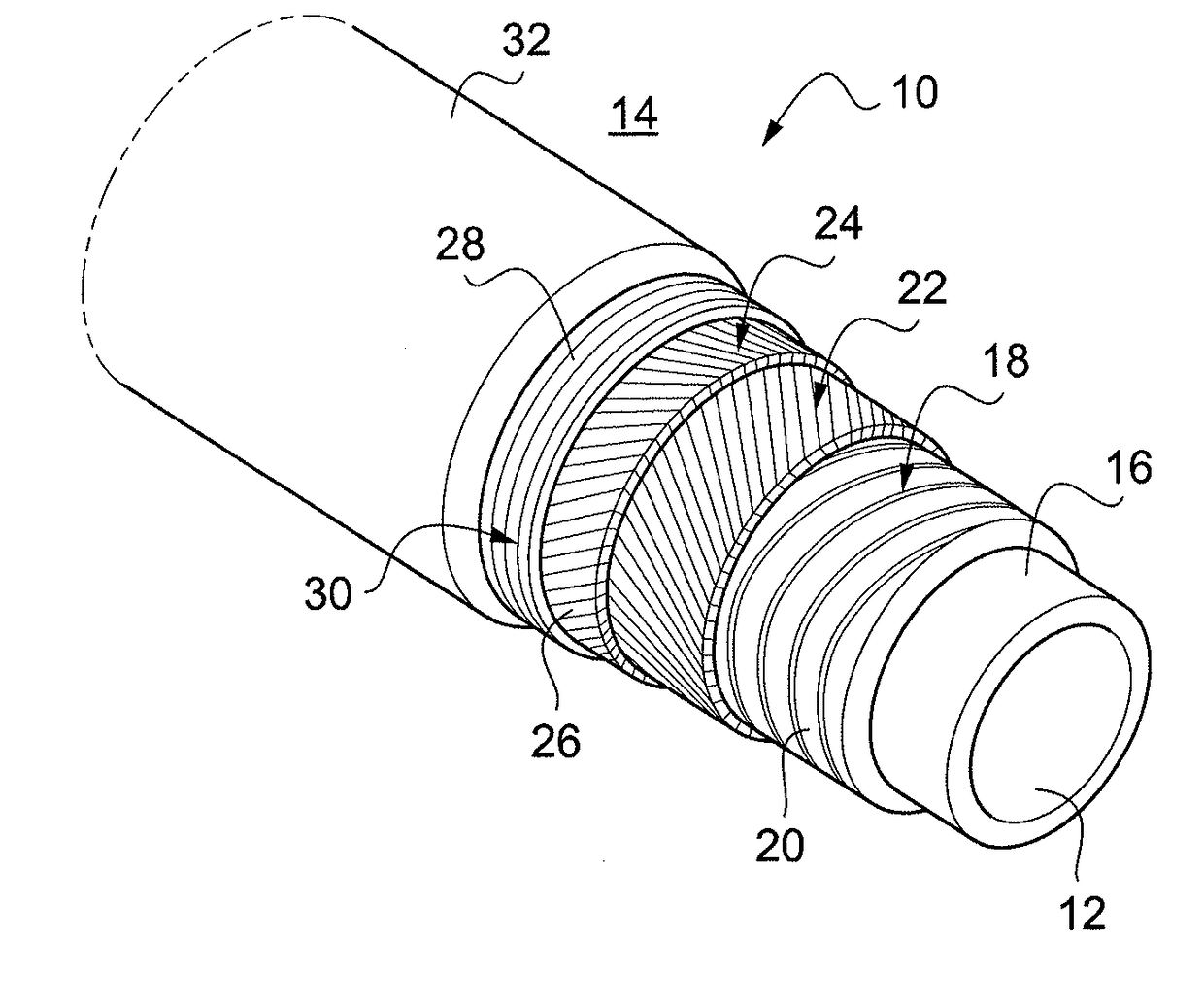
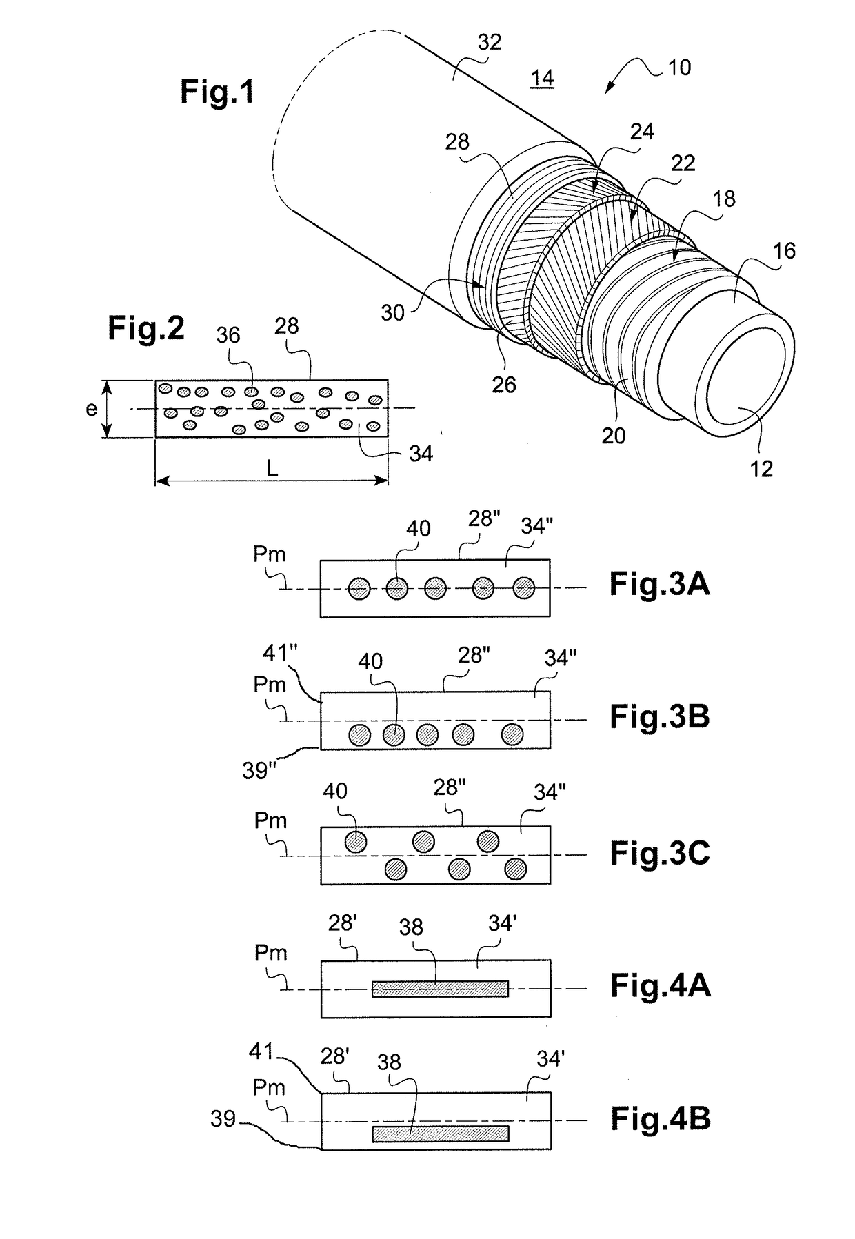
[0032]FIG. 1 illustrates in partial cutaway view a flexible tubular pipe 10, showing the different superposed layers of which it is composed. These are consecutively produced one on top of the other, from the inside 12 of the pipe to the outside 14. The inside 12 forms an internal flow space for the hydrocarbon.

[0033]The innermost layer is a pressure sheath 16 realized from a polymer material by hot extrusion. The polymer material used is advantageously a semi-crystalline thermoplastic material. This pressure sheath 16 is tight and thick enough to be able to resist the pressurized and possibly hot flow of a hydrocarbon.

[0034]Next, the pressure sheath 16 is covered by a pressure vault 18 made of a metallic wire with a substantially rectangular cross section, wound in a short-pitch spiral to form contiguous turns 20. The turns 20 will be applied radially against the pressure sheath 16. The pressure vault 18 is thus able to absorb the external forces exerted radially by the hydrostatic...


PUM

PropertyMeasurementUnit
Thicknessaaaaaaaaaa
Flexibilityaaaaaaaaaa

Abstract

A flexible tubular conduit (10) having a tubular inner pressure structure including a tubular sheath (16) and a pressure vault (18) for taking up the radial forces, and a tubular outer tensile structure having at least one web of tensile armor wires (22, 24), and a holding strip (28) wound in a short-pitch helix over the web of tensile armor wires (24), the holding strip (28) comprising a layer of polymer material and a plurality of strands of fibers stretched substantially in the longitudinal direction of the holding strip (28). The fibers of the strands of the plurality of strands of fibers are mineral fibers, and the plurality of strands of fibers is embedded in the layer of polymer material.

Description

CROSS-REFERENCE TO RELATED APPLICATIONS[0001]The present application is a 35 U.S.C. §§371 national phase conversion of PCT / FR2015 / 051572, filed Jun. 15, 2015, which claims priority of French Patent Application No. 1455486, filed Jun. 16, 2014, the contents of which are incorporated by reference herein. The PCT International Application was published in the French language.TECHNICAL FIELD[0002]The present invention relates to a flexible tubular pipe designed for the transport of hydrocarbons.[0003]One contemplated field of application is particularly, but not exclusively, that of the transport of hydrocarbons in a marine environment between a marine bottom and an overlying surface.BACKGROUND OF THE INVENTION[0004]So-called “unbonded” flexible tubular pipes are described in the normative documents API 17J, “Specification for Unbonded Flexible Pipe”, API RP 17B, “Recommended Practice for Flexible Pipe”, API 17J, “Specification for Unbonded Flexible Pipe”, API 16C, “Choke and Kill Syste...

Claims


Application Information

Patent Timeline
IPC IPC(8): F16L11/08F16L11/02
CPCF16L11/083F16L11/088F16L11/02B29C70/52
Inventor DEMANZE, FREDERIC
Owner TECH FRANCE SA
Why Eureka
Try Eureka