Eureka AIR delivers breakthrough ideas for toughest innovation challenges, trusted by R&D personnel around the world.

Polarization Resistant Solar Cell Design Using an Oxygen-Rich Interface Layer

Inactive Publication Date: 2011-04-28
SUNNUVELLIR SLHF
View PDF13 Cites 11 Cited by
  • Summary
  • Abstract
  • Description
  • Claims
  • Application Information

AI Technical Summary

Benefits of technology

[0007]The present invention provides a solar cell that is resistant to the

Problems solved by technology

Solar cells are becoming commonplace in a wide range of applications, both due to the increase in energy costs and the growing environmental concerns associated with traditional energy sources.
As a result, shunt resistance and p-n junction characteristics are significantly degraded, leading to a major reduction in cell conversion efficiency and potentially complete cessation of cell power output.

Method used


Image

  • Polarization Resistant Solar Cell Design Using an Oxygen-Rich Interface Layer
  • Polarization Resistant Solar Cell Design Using an Oxygen-Rich Interface Layer
  • Polarization Resistant Solar Cell Design Using an Oxygen-Rich Interface Layer

Examples


Embodiment Construction

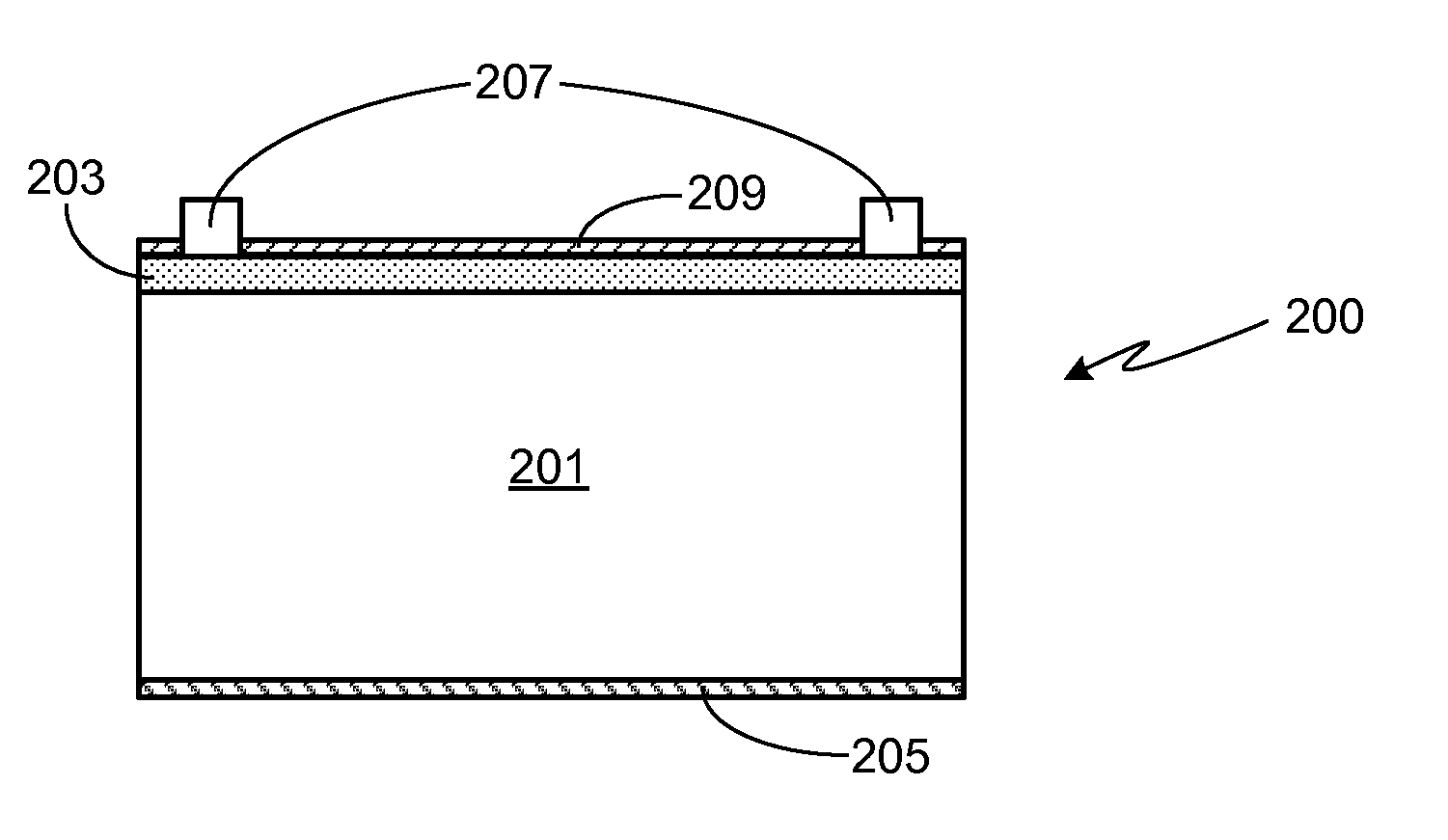
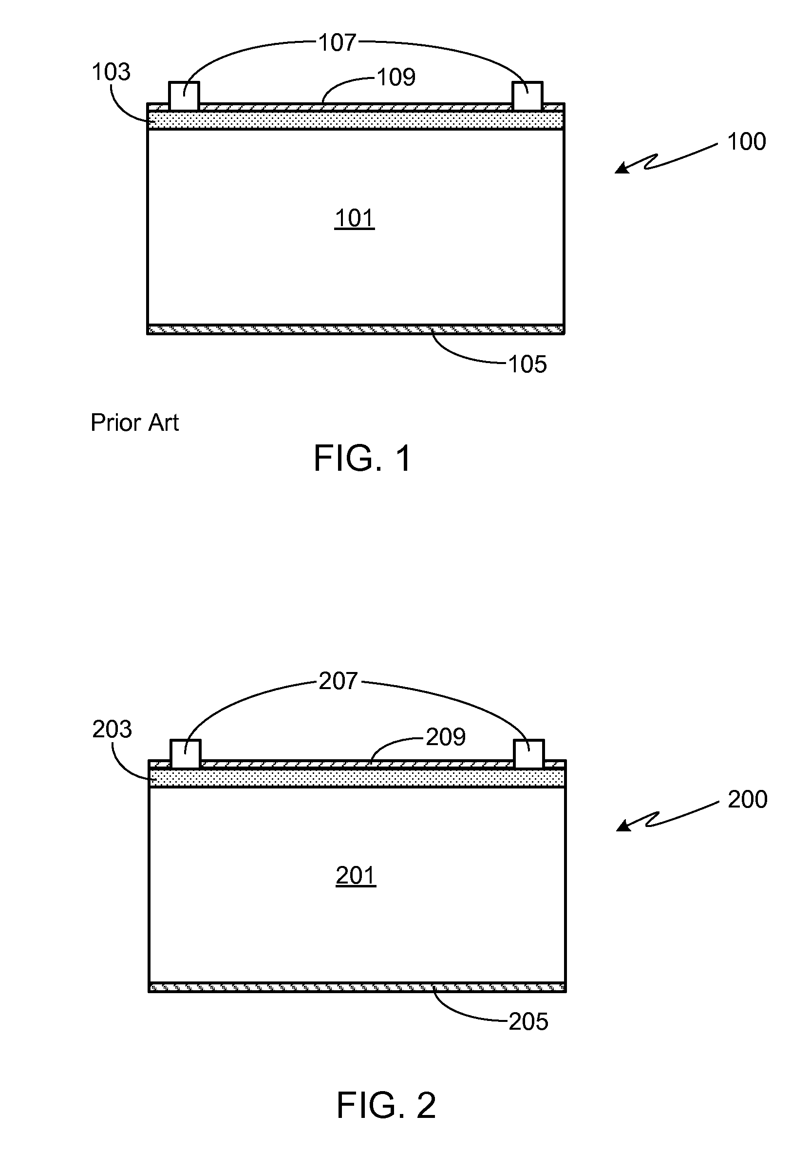
[0018]The inventors have found that the incorporation of an oxygen-rich interface layer in the solar cell design can substantially reduce, if not altogether eliminate, the device degradation that typically occurs in a conventional solar cell that is subjected to a large electric field across the dielectric layer(s). FIG. 2 provides a cross-sectional view of a solar cell device structure 200 in accordance with a preferred embodiment of the invention. Silicon substrate 201 may be of either p- or n-type. As with a conventional solar cell, a silicon layer 203 of a second conductivity type is formed on substrate 201, thereby forming the cell's p-n junction. A rear surface electrode 205, for example comprised of aluminum, contacts at least a portion of substrate 201 or, as shown, the entire back surface of the substrate. To contact the front surface of the device, more specifically layer 203, preferably a plurality of front surface electrodes 207, preferably comprised of silver, are appli...


PUM


Abstract

A polarization resistant solar cell using an oxygen-rich interface layer is provided. The oxygen-rich interface layer may be comprised of SiOxNy, which may have a graded profile that varies between oxygen-rich proximate to the solar cell to nitrogen-rich distal to the solar cell. A silicon oxide passivation layer may be interposed between the solar cell and the SiOxNy graded dielectric layer. The graded SiOxNy dielectric layer may be replaced with a non-graded SiOxNy dielectric layer and a SiN AR coating.

Description

CROSS-REFERENCE TO RELATED APPLICATION[0001]This application claims the benefit of the filing date of U.S. Provisional Patent Application Ser. No. 61 / 279,842, filed Oct. 27, 2009, the disclosure of which is incorporated herein by reference for any and all purposes.FIELD OF THE INVENTION[0002]The present invention relates generally to solar cells and, in particular, to a polarization resistant solar cell design.BACKGROUND OF THE INVENTION[0003]Photovoltaic cells, commonly referred to as solar cells, are well known semiconductor devices that convert photons into electrical energy. FIG. 1 provides a cross-sectional view of a conventional solar cell 100 that includes a substrate 101 of a first conductivity type, the substrate frequently comprised of silicon, and a layer 103 of a second conductivity type formed on the substrate, commonly referred to as the emitter, thereby forming a p-n junction at the interface. Solar cell 100 also includes a rear surface electrode 105 that is in contac...

Claims


Application Information

Patent Timeline
IPC IPC(8): H01L31/00
CPCH01L31/02167Y02E10/50H01L31/1868H01L31/02168Y02P70/50H01L31/04H01L31/0216
Inventor PHAN, BILLZHANG, RENHUAGORMAN, JOHNSIDELKHEIR, OMARRAKOTONIAINA, JEAN PATRICEBLOSSE, ALAIN PAULKAES, MARTIN
Owner SUNNUVELLIR SLHF
Why Eureka
Eureka Blog
Learn More