Eureka AIR delivers breakthrough ideas for toughest innovation challenges, trusted by R&D personnel around the world.

Method for producing spring rails for windshield wipers

Inactive Publication Date: 2013-09-17
STAHLWERK ERGSTE WESTIG
View PDF15 Cites 0 Cited by
  • Summary
  • Abstract
  • Description
  • Claims
  • Application Information

AI Technical Summary

Benefits of technology

The invention relates to a coated spring rail which is used in windscreen wipers. The coating has three layers and is constructed in a way that it can be welded onto the wiper blade using a process called vibration welding. This process is fast and cost-effective. The coated spring rail can also be joined with plastic materials that surround or penetrate the wiper blade. However, vulcanizing is not suitable because of cost considerations. This patent aims to provide a solution for joining the wiper blade and spring rail in a durable and cost-effective way.

Problems solved by technology

Due to the spring-elasticity of the spring rail, oscillations may occur, in particular characteristic or resonance oscillations, which may cause the wiper edge to partially lift off, thereby significantly reducing the visibility through the vehicle windshield.
This is supposed to result in a quieter wiper operation.
Disadvantageously, however, the oscillation characteristic is only reduced for a few fixed frequencies, so that the changing operating and oscillation behavior in practical applications cannot be satisfactorily eliminated.
In addition, using the different spring rails requires complex assembly and also increases inventory costs.
The elastic oscillations which are undesirable in windshield wipers are generally caused by the low damping of the spring steels used for the spring rails.
This is disadvantageous and unfavorable with windshield wipers, because it can cause rattling.
Rattling may severely interfere with the operation, reduce the service life of the wiper rail and also present a safety risk.
Inserting the spring rail into recesses or guide channels of the wiper blade, however, does generally not produce sufficient damping of oscillations, because the spring rail—even when embedded—still has degrees of freedom for oscillations.
In practice, this can cause relative movement between the spring rail and the wiper blade, thereby preventing uniform wiping at high vehicle speeds or during wind turbulences.
This results in undesirable and detrimental rattle oscillations which have a negative effect in particular at high vehicle speeds.

Method used


Image

  • Method for producing spring rails for windshield wipers
  • Method for producing spring rails for windshield wipers
  • Method for producing spring rails for windshield wipers

Examples


Embodiment Construction

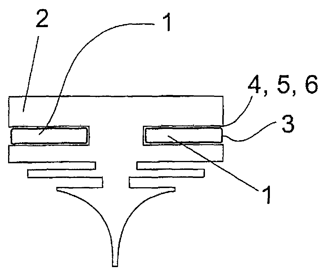
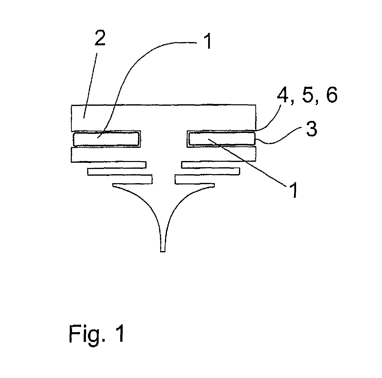
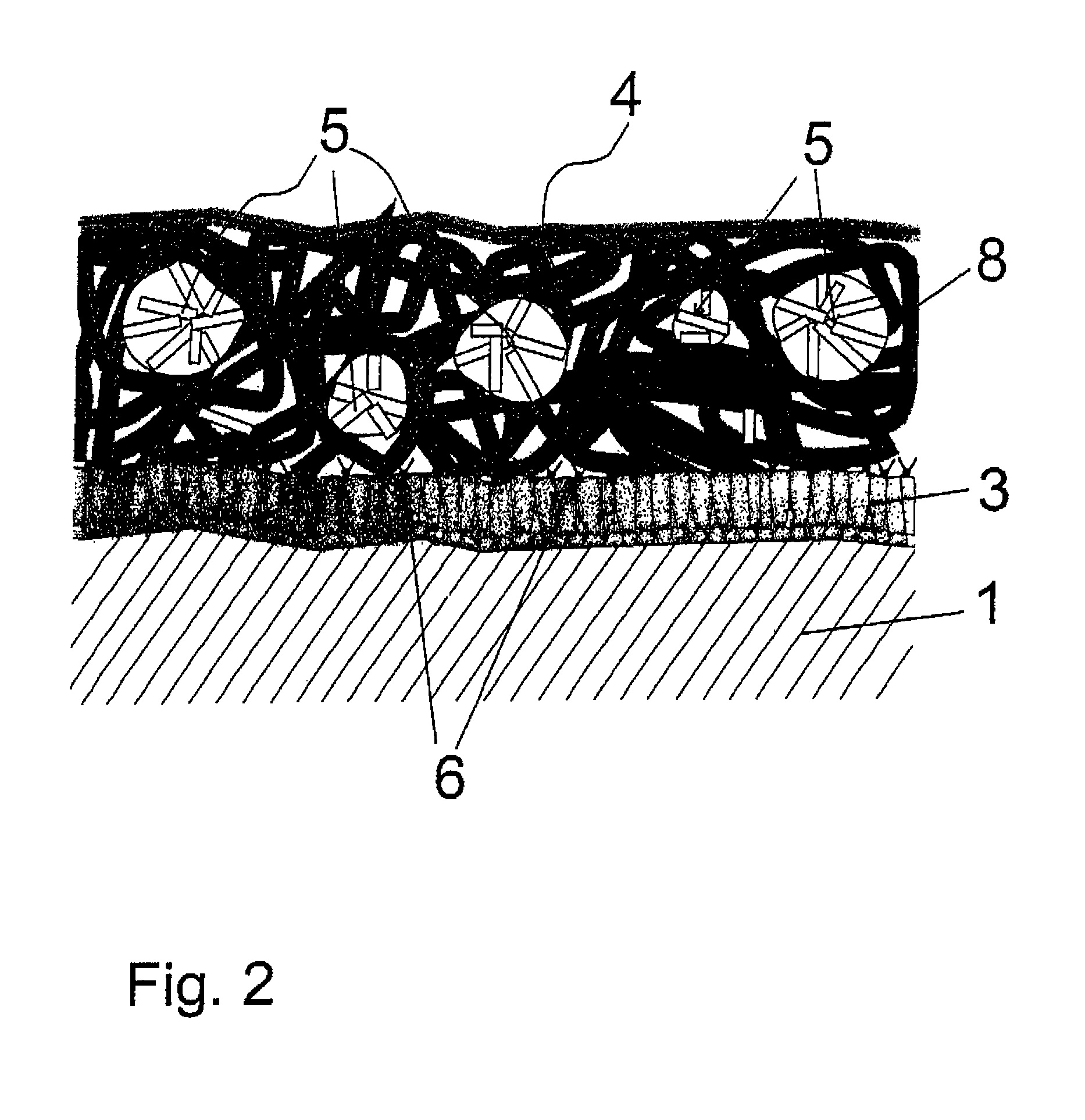
[0040]The spring rail 1 according to the invention is made of steel and is provided with a conventional wiper blade 2. The spring rail 1 has a total of three layers, a base layer 3 made of zinc, a cover layer 4 with partially crystalline components 5 that are soluble in CHCl3, and an intermediate reaction or anchor layer 6 made of anchor molecules in a typical embedding material 7 (FIG. 3), which is used merely for embedding the sample.

[0041]The base layer 3 is composed of zinc or a zinc alloy with up to 15% nickel, iron and cobalt, separately or in combination. The base layer 3 is applied galvanically in an electrolytic bath directly onto the surface of the metallic spring rail 1. The base layer 3 has a thickness d1 from 2 to 20 μm, preferably from 3 to 10 μm.

[0042]The zinc contains in the anchor layer 6, i.e., into transition region to the cover layer 4, oxygen-rich anchor compounds intended to bond or anchor the layers 3 and 4 with each other via molecular forces.

[0043]Zinc compo...


PUM

PropertyMeasurementUnit
Temperatureaaaaaaaaaa
Fractionaaaaaaaaaa
Fractionaaaaaaaaaa

Abstract

The invention relates to a method for producing coated spring-loaded steel rails especially for windshield wipers comprising a rubber or elastomer wiper blade, wherein a cold-rolled steel rail blank is provided with a zinc layer, whereafter a zinc-containing anchor layer is produced, and a coating made of a polymerizable coating powder is deposited on the anchor layer and partially cured.

Description

CROSS-REFERENCES TO RELATED APPLICATIONS[0001]This application is the U.S. National Stage of International Application No. PCT / EP2009 / 001117, filed Feb. 18, 2009, which designated the United States and has been published as International Publication No. WO 2009 / 106250and which claims the priority of German Patent Applications, Ser. No. 10 2008 012 083.9, filed Feb. 29, 2008, and Ser. 10 2008 014 938.1, filed Mar. 19, 2008, pursuant to 35 U.S.C. 119(a)-(d)BACKGROUND OF THE INVENTION[0002]The invention relates to a method for producing spring rails made of steel, in particular for windshield wipers having a rubber or elastomer wiper blade.[0003]Conventional windshield wipers for automobiles include a wiper arm which is supported on a wiper shaft and are driven by a wiper motor. A spring rail with a wiper blade made of rubber is arranged at the end on the wiper arm and frequently attached in an articulated manner. The wiper blade has a wiper edge used to remove water and / or dirt adheri...

Claims


Application Information

Patent Timeline
IPC IPC(8): B32B37/00
CPCB05D7/14B05D2350/00B60S2001/3898B05D2401/32B60S1/3879B05D2350/65
Inventor CASTRO, VICTORPACHER, OSKAR
Owner STAHLWERK ERGSTE WESTIG
Why Eureka
Eureka Blog
Learn More