
Isochronous timepiece resonator

a timepiece resonator and oscillator technology, applied in the field of isochronous timepiece oscillator mechanism, can solve the problems of limiting the quality factor of the resonator, system is still sensitive to shock, and large movement of the centre of mass, so as to improve the quality factor, reduce the sensitivity to changes in position, and improve the quality factor

Active Publication Date: 2017-05-04
ETA SA MFG HORLOGERE SUISSE
View PDF6 Cites 12 Cited by
  • Summary
  • Abstract
  • Description
  • Claims
  • Application Information

AI Technical Summary

Benefits of technology

The patent text describes a timepiece movement that uses a special type of oscillator to keep track of time. This helps to ensure that the movement is accurate and reliable. The invention can also be applied to other devices that need to keep track of time, such as computers and smartwatches. Its technical effects include improved accuracy and reliability in keeping track of time and other related applications.

Problems solved by technology

In a conventional mechanical watch, air friction on the balance wheel, the friction of the pivots in their bearings and the reaction forces of the balance spring stud limit the quality factor of the resonator.
However, the centre of mass moves a great deal, and this system is still sensitive to shocks.

Method used


Image

  • Isochronous timepiece resonator
  • Isochronous timepiece resonator
  • Isochronous timepiece resonator

Examples


first embodiment

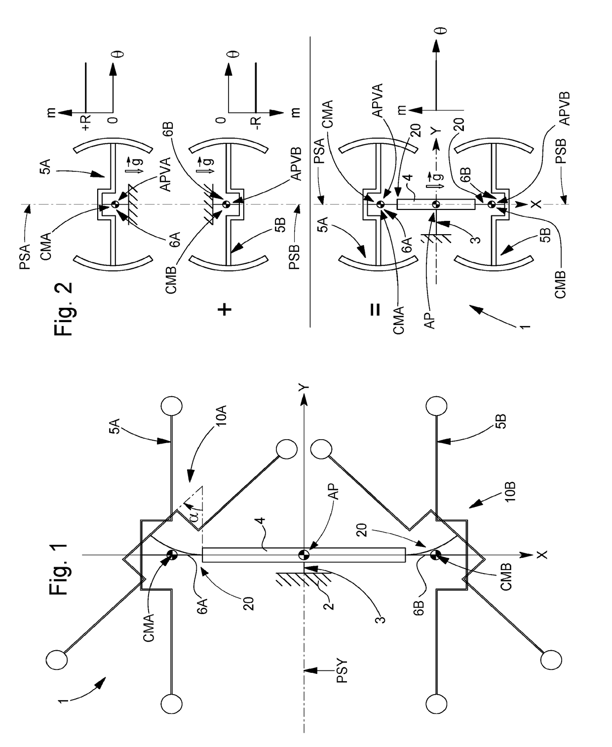
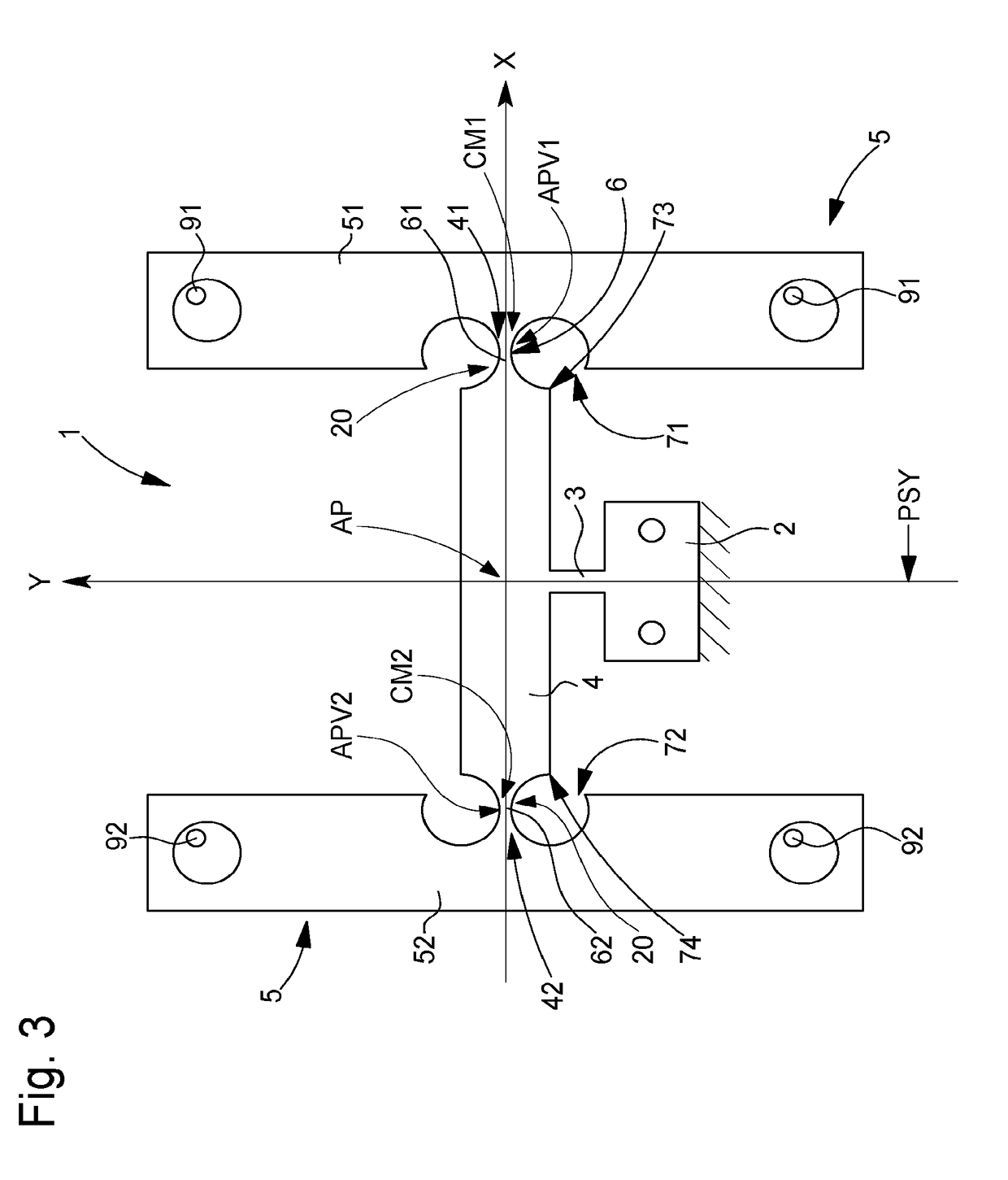
[0117]In the variant of FIGS. 1 to 8, detailed below, flexible elastic strips 6 are straight, in longitudinal direction X. The centres of mass CM of the primary resonators 10 concerned are in alignment at rest. This arrangement ensures that isochronous oscillator mechanism 1 according to the invention is unaffected by positions in space, unlike a conventional tuning fork with parallel prongs which is far too sensitive to positions in space if it is incorporated in a watch, and which is only suitable for a clock.

[0118]The sketch of FIG. 2 explains the effect of gravity {right arrow over (g)}:[0119]in the top sketch, on a first weight suspended towards the top via a flexible strip, the rate diagram illustrates a losing rate of a certain value R,[0120]in the middle sketch, on a second identical weight suspended towards the bottom via an identical flexible strip, and the rate diagram corresponding to a gain in rate of the same value R,[0121]in the bottom sketch, on a mechanism accordin...

second embodiment

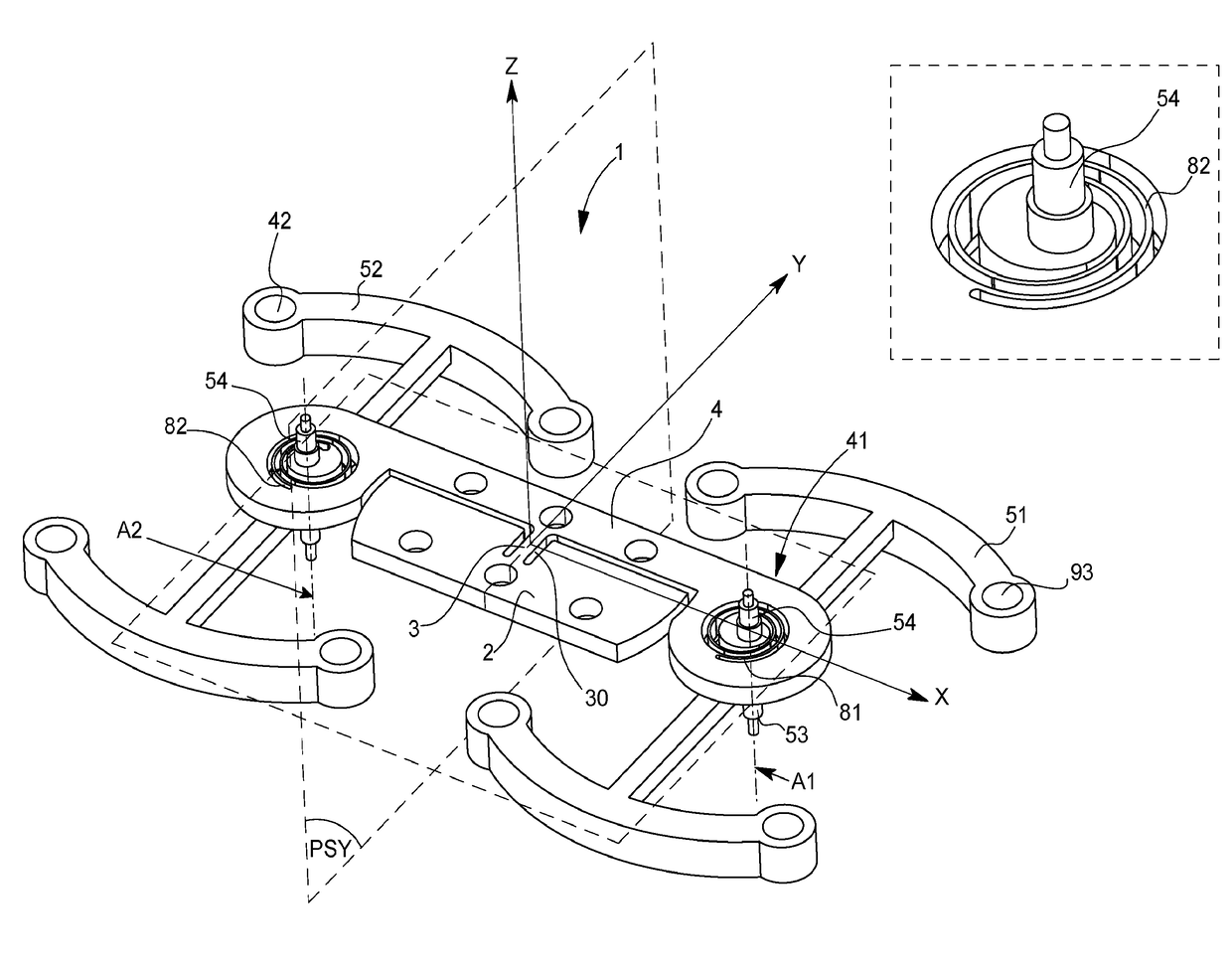
[0126]In the variants of FIGS. 9 to 12, detailed below, flexible bearings 20 are formed by flexible elastic strips 6 in spirals, wound around centres of mass CM of the primary resonators 10 concerned.

[0127]A variant illustrated in FIGS. 13 and 14 represents a torsional tuning fork which comprises prongs 51 and 52, each provided with a weight at its distal end, and oscillating in parallel planes P1 and P2 and symmetrically with respect to an axis A parallel to these two planes P1 and P2.

[0128]Another tuning fork variant illustrated by FIG. 15 comprises two resonators, each including a balance spring attached at a first end to a common crosspiece and comprising a weight at a second distal end; these two resonators extend in two parallel planes and, in projection onto one of the planes, are symmetrical with respect to a plane of symmetry PS which is perpendicular to said two planes. The resulting torque is zero at the point of attachment on crosspiece 4.

[0129]It is understood that the...


PUM


Abstract

A watch including a movement including itself an isochronous timepiece oscillator mechanism including a fixed support bearing a crosspiece carrying N primary resonators each including a weight carried by a rotating flexible bearing fixed to this crosspiece. Each primary resonator has a center of mass which, at rest, is on the virtual pivot axis of its rotating flexible bearing and is arranged to oscillate in rotation about this virtual pivot axis. The primary resonators are arranged in rotational symmetry of order N about a main axis parallel to the virtual pivot axes, and oscillating motions of any two primary resonators are phase shifted by the value of the central angle formed by their respective virtual pivot axes with the main axis.

Description

FIELD OF THE INVENTION[0001]The invention concerns an isochronous timepiece oscillator mechanism, comprising a fixed support which bears a crosspiece carrying a plurality of N primary resonators each including at least one weight carried by a rotating monolithic articulated structure or flexible bearing fixed to said crosspiece.[0002]The invention also concerns a timepiece movement comprising at least one such isochronous oscillator mechanism.[0003]The invention also concerns a watch including at least one movement of this type.[0004]The invention concerns the field of oscillator and regulating mechanisms for timepieces, in particular for mechanical movements.BACKGROUND OF THE INVENTION[0005]In a conventional mechanical watch, air friction on the balance wheel, the friction of the pivots in their bearings and the reaction forces of the balance spring stud limit the quality factor of the resonator. It is sought to eliminate pivot friction and the forces of reaction at the point of at...

Claims


Application Information

Patent Timeline
Patent Type & Authority Applications(United States)
IPC IPC(8): G04C3/08
CPCG04C3/08G04B17/045G04B17/10G04B17/28G04B17/06G04B17/066G04B43/002G04B15/06G04B15/14G04B15/02G04B5/04
Inventor WINKLER, PASCALHELFER, JEAN-LUCDI DOMENICO, GIANNICONUS, THIERRY
Owner ETA SA MFG HORLOGERE SUISSE
Learn More