
Parameter Design Method of Coupling Mechanism to Restrain Planar Metal Effect of Pickup Coil

A technology for picking up coils and coupling mechanisms, applied in transformer/inductor coils/windings/connections, preventing/reducing unwanted electrical/magnetic influences, transformer/inductor components, etc., can solve eddy current losses, system parameters Detuning and other problems, to achieve the effect of long transmission distance and high transmission efficiency

Active Publication Date: 2022-01-28
CHONGQING UNIV
View PDF14 Cites 0 Cited by
  • Summary
  • Abstract
  • Description
  • Claims
  • Application Information

AI Technical Summary

Problems solved by technology

[0004] In view of the mutual coupling between the pickup coil of the existing wireless power transmission system and its coplanar metal, which leads to system parameter detuning and eddy current loss, etc., in order to suppress the influence of the metal on the coupling mechanism parameters and system performance, improve the performance of the MC-WPT system in the metal environment. applicability, the present invention provides a coupling mechanism parameter design method that suppresses the influence of the pick-up coil plane metal

Method used


Image

  • Parameter Design Method of Coupling Mechanism to Restrain Planar Metal Effect of Pickup Coil
  • Parameter Design Method of Coupling Mechanism to Restrain Planar Metal Effect of Pickup Coil
  • Parameter Design Method of Coupling Mechanism to Restrain Planar Metal Effect of Pickup Coil

Examples


Embodiment 1

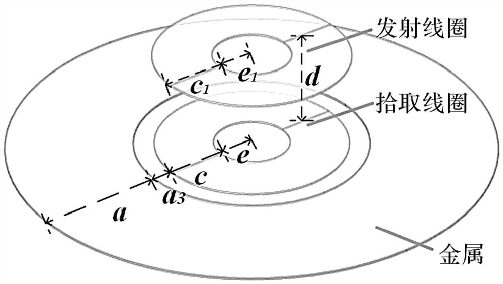
[0056] In order to weaken the magnetic flux passing through the metal around the coil through the coupling mechanism, reduce the coupling between this part of the metal and the pickup coil, and realize the effect of suppressing the influence of the metal on the coil parameters, this embodiment designs a method of suppressing the pickup coil plane based on the above discussion. Coupling mechanisms influenced by metals, such as Figure 7 , 8 shown (reserved figure 1 Parameters of the same attribute in ), including the pick-up coil and the transmit coil separated by the transmission distance d from the pick-up coil;

[0057] The pick-up coil includes a main coil (inner diameter e, outer diameter c), and a suppression coil (inner diameter g, outer diameter l) drawn from the end of the main coil and rewinding the main coil, the main coil and the suppression coil are separated by a first preset distance a 4 ; Both the main coil and the suppression coil are circular, the inner dia...

Embodiment 2

[0069] The present invention also provides a parameter design method applied to the coupling mechanism that suppresses the influence of surrounding metals as described in Embodiment 1, such as Figure 14 shown, including steps:

[0070] S1. Determine the frequency of the pickup coil described in Embodiment 1 and the window size r of the metal plate surrounding the pickup coil according to the application requirements, r=l+a 3 , a 3 is the gap width between the metal plate and the pickup coil;

[0071] S2. According to the window size r of the metal plate and the first to fourth adjustable parameters a 1 ~a 4 Determine the size of the pickup coil, including the inner diameter e of the main coil, the outer diameter c, and the number of turns of the suppression coil n 1 , outer diameter l and inner diameter g;

[0072] S3. Verify the pickup coil determined in step S2, and adjust the first to fourth adjustable parameters a 1 ~a 4 Or directly modify the number of turns n of ...

Embodiment 3

[0088] This embodiment provides an MC-WPT system, including a transmitting end and a receiving end. The transmitting end includes the transmitting coil in the coupling mechanism of Embodiment 1, and the receiving end includes the pickup coil (pickup coil) in the coupling mechanism of Embodiment 1.

[0089] The transmitter also includes a Figure 5 The DC source, the inverter bridge, and the LCC resonant network connected in the same order, and the LCC resonant network is connected to the transmitting coil; the receiving end also includes a Figure 5 The resonance compensation capacitor, rectifier bridge, filter capacitor and load are connected in the same order, and the resonance compensation capacitor is connected to the pickup coil.

[0090] The MC-WPT system provided in this embodiment is based on the coupling mechanism described in Embodiment 1, and related transmission lines are built, and the above coupling mechanism is applied in actual work, such as docking and chargin...


PUM


Abstract

The present invention relates to the technical field of magnetic coupling wireless power transmission, and specifically discloses a coupling mechanism parameter design method that suppresses the influence of pickup coil plane metal. The coupling mechanism includes a pickup coil and a transmitting coil separated from the pickup coil by a transmission distance d; Coil, and the suppression coil drawn from the end of the main coil and rewinding the main coil, the inner diameter of the suppression coil is g, the outer diameter is l, and the first preset distance a is separated between the main coil and the suppression coil 4 ; Both the main coil and the suppression coil are circular, the inner diameter of the main coil is e, and the outer diameter is c. The pick-up coil reversely winds the suppression coil outside the main coil, which can suppress the magnetic flux coupled with the metal environment outside the coil range, weaken the influence of metal on the coil self-inductance, internal resistance, and mutual inductance, and improve the MC-WPT system on the metal plane. Work efficiency, reduce the eddy current loss generated in the metal during MC‑WPT work, and improve the safety of the MC‑WPT system. Moreover, the coupling mechanism has a simple structure and is easy to popularize and apply.

Description

technical field [0001] The invention relates to the technical field of magnetic coupling wireless power transmission, in particular to a coupling mechanism parameter design method for suppressing the influence of pickup coil plane metal. Background technique [0002] In recent years, with the development of Magnetic field Coupled Wireless Power Transfer (MC-WPT) technology, MC-WPT technology has been popularized and applied in many fields, but it also brings a series of challenges, especially some special within the working environment. The spacecraft power supply and distribution system is responsible for the important task of providing, storing, regulating and distributing electrical energy to the spacecraft platform and loads. Once a failure occurs, astronauts may need on-orbit maintenance. In order to prevent the astronauts from being shocked by plugging and unplugging the connectors, the maintenance and replacement of the power supply and distribution system requires c...

Claims


Application Information

Patent Timeline
Patent Type & Authority Patents(China)
IPC IPC(8): H02J50/12H02J50/70H02J50/90H01F27/28H01F27/34H01F38/14
CPCH02J50/12H02J50/70H02J50/90H01F27/2804H01F27/34H01F38/14H01F2027/2809H01F2027/348
Inventor 苏玉刚刘家鸣孙跃王智慧唐春森戴欣
Owner CHONGQING UNIV
Learn More