
Acoustic bandgap structures adapted to suppress parasitic resonances in tunable ferroelectric capacitors and method of operation and fabrication therefore

a technology of ferroelectric capacitors and band gaps, applied in the direction of fixed capacitors, variable capacitors, fixed capacitor details, etc., can solve the problems of reducing the quality factor of tunable ferroelectric capacitors

Active Publication Date: 2009-03-05
NXP USA INC
View PDF5 Cites 7 Cited by
  • Summary
  • Abstract
  • Description
  • Claims
  • Application Information

AI Technical Summary

Benefits of technology

[0010]Still another embodiment of the present invention may provide for a method for improving the quality factor of a tunable ferroelectric capacitor, comprising selecting ferroelectric layers and conductive electrode layers to form unit cells, fabricating the unit cells into one-dimensional periodic structures and selecting the thicknesses of each layer to form an acoustic bandgap over the frequency range where the quality factor is desired to be improved. The method may further comprise rendering acoustically inert all ferroelectric layers except for one or two intentionally tunable layers by electrically shorting the electrodes on opposite sides of the remaining ferroelectric layers.

Problems solved by technology

They are also damped by acoustic radiation loss into the substrate.
Both loss mechanisms will reduce the height of the ESR peak, but they will deleteriously broaden the peak or the frequency range over which ESR is increased.
Acoustic resonances have recently been recognized as an issue in the design of tunable ferroelectric capacitors since they result in degradation of device Q at microwave frequencies.
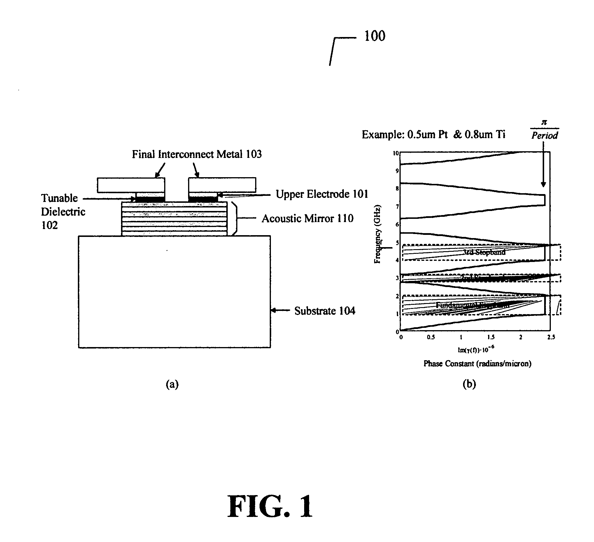
However, the acoustic mirror or Bragg reflector as described above does not prevent acoustic resonances.

Method used


Image

  • Acoustic bandgap structures adapted to suppress parasitic resonances in tunable ferroelectric capacitors and method of operation and fabrication therefore
  • Acoustic bandgap structures adapted to suppress parasitic resonances in tunable ferroelectric capacitors and method of operation and fabrication therefore
  • Acoustic bandgap structures adapted to suppress parasitic resonances in tunable ferroelectric capacitors and method of operation and fabrication therefore

Examples


first embodiment

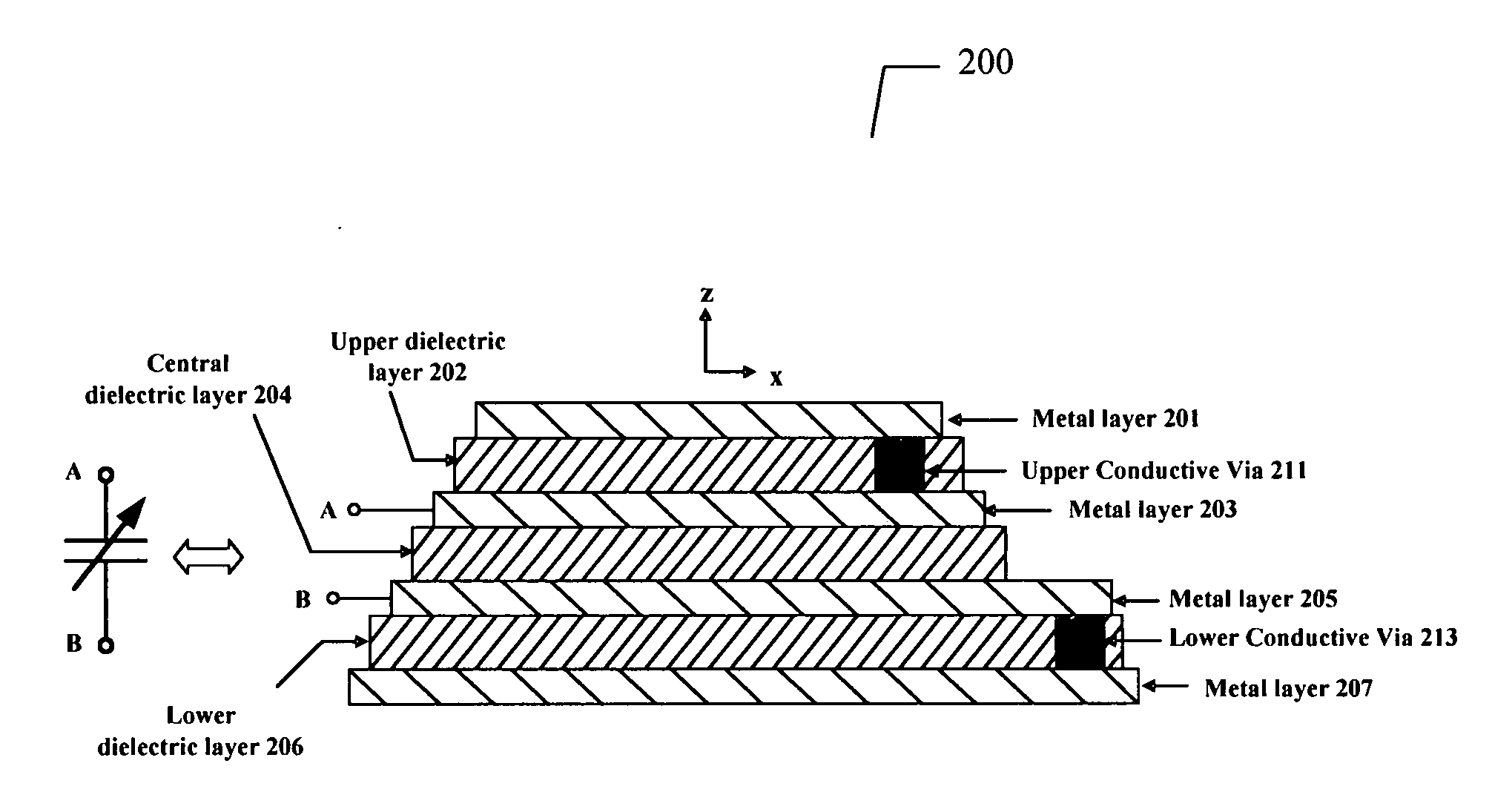
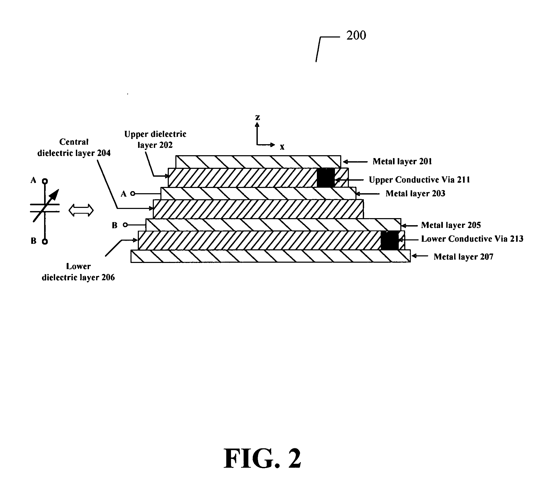
[0034]Turning now to FIG. 2 at 200 is the present invention. This is a thin film tunable capacitor fabricated as a layered structure in the z direction. Dielectric layers 202, 204, and 206 are stacked ferroelectric layers of essentially the same acoustic characteristic impedance and the same thickness. The ferroelectric material may be BaSrTi, BaSrTiO, SrTiO, or any other voltage dependent dielectric film. These dielectric layers are sandwiched between conductive electrode layers which are described in FIG. 2 as metal layers 201, 203, 205, and 207. These metal layers have essentially the same acoustic characteristic impedance and the same thickness. Typically these metal layers would be identical materials, but not necessarily and the present invention is not limited to this. Given these restrictions, the structure of FIG. 2 is a 1D periodic acoustic structure.

[0035]Furthermore, metal layers 201 and 203 may be electrically shorted together by a conductive via 211. Metal layers 205 a...

second embodiment

[0037]the present invention is an extension of stacked tunable capacitors where the middle electrode (metal layer 305) is biased at a DC voltage and the top and bottom electrodes (metal layers 303 and 307) are held at ground voltage. This biasing scheme ensures that the biasing electric fields in dielectric regions 304 and 306 are antipodal, or counter-directed. When so biased, the superimposed RF fields will launch acoustic waves from dielectric layers 304 and 306 that essentially cancel each other at a certain frequency associate with the lowest acoustic resonance of the structure. However, certain higher order acoustic modes will not cancel and this is the reason for the ABG structure.

[0038]To predict the acoustic bandgaps (ABGs) that may be realized from the aforementioned embodiments, one may approximate the stack with an equivalent transmission line model of an infinite periodic structure. A unit cell is identified and its ABCD parameters are calculated. Given parameters A and...

embodiment b

[0057 shown in FIG. 3 may also be modeled using Mason's model for the acoustically active layers. One such model, shown in FIG. 18 generally as 1800, allows the calculation of electrical impedance and Q. Note that the secondary of the two transformers is wired differently to produce opposite phases of longitudinal movement in the dielectric layers 304 and 306. This is needed because, in FIG. 3, the DC biasing electric fields are oppositely directed across layers 304 and 306. Also in this model is the assumption that the capacitor structure is suspended in air. However, mounting this structure solidly to a substrate will not affect the electrical performance (Zin or Q) in any significant way within the ABG frequency range since the ABG is defined by the tunable dielectric layers and its near neighbors.

[0058]Note that the acoustic circuit models shown herein may use simple transmission lines for the acoustically inert layers. Alternatively, such layers may be modeled using passive T-n...


PUM


Abstract

An embodiment of the present invention is an apparatus, comprising a stack of at least three ferroelectric layers with a top side and bottom side of each of the ferroelectric layers contacting an electrode layer, wherein the ferroelectric layers and the electrode layers form a substantially periodic structure in the direction normal to said ferroelectric and electrode layers and wherein an acoustic characteristic impedance and thickness of each layer are selected to realize an acoustic bandgap over a desired frequency band for the purpose of improving device Q.

Description

BACKGROUND[0001]Tunable thin film ferroelectric capacitors may be fabricated on conventional sapphire or alumina substrates using films of BST, BSTO, SrTiO?, etc. Such films are tunable because their normal component of dielectric constant can be reduced with an applied electric field. However, these films are also electrostrictive, meaning that the thickness of the thin films is also changed as a function of applied electric field. When an RF electric field is applied across an electrostrictive film, a force or stress appears in the film. This stress causes a strain or motion in the molecules of the film. Bulk acoustic waves in the form of longitudinal waves are generated within that film layer in the direction normal to the interfaces. Hence electric energy is transformed into acoustic energy. This phenomenon is well known to designers of microwave acoustic resonators. See for example the tutorial paper by Weigel et. al. (IEEE Trans. on Microwave Theory and Techniques, Vol. 50, No...

Claims


Application Information

Patent Timeline
Patent Type & Authority Applications(United States)
IPC IPC(8): H01G7/06
CPCH01G7/06H01G4/30
Inventor MCKINZIE, III, WILLIAM E.
Owner NXP USA INC
Learn More