
Compact lens assembly

a technology of compact lenses and lens assemblies, applied in the field of compact lenses, can solve the problems of greatly reducing the temperature sensitivity of the lens front element, and achieve the effects of low sensitivity to temperature changes, reduced lens temperature sensitivity, and less costly manufacturing

Inactive Publication Date: 2005-01-20
NING ALEX
View PDF4 Cites 14 Cited by
  • Summary
  • Abstract
  • Description
  • Claims
  • Application Information

AI Technical Summary

Benefits of technology

[0007] The above-noted problems, and others, are overcome in accordance with this invention by a lens for digital cameras; in particular, such cameras that are incorporated into another device such as a cell phone, personal digital assistant and the like, that is extremely compact and has a short length from the front element surface to the imaging plane, have three lens elements having excellent optical characteristics.
[0009] In the preferred embodiment, an IR cut-off coating is also applied to the second surface of the third lens element to produce an integrated imaging lens with IR cut-off function. This eliminates the need for a separate IR cut-off filter in addition to the lens, thus making the entire optical assembly less costly to manufacture.
[0010] In the preferred embodiment, the first lens element is also made of glass material. The use of a glass front element greatly reduces lens temperature sensitivity when the lens is taken from areas at great temperature differences, such as when bringing a camera into a building on a hot summer day or cold winter day.
[0011] It is, therefore, an object of this invention to provide a compact lens assembly particularly suitable for use in high resolution compact digital cameras with megapixel imagers, especially those incorporated into other compact electronic devices such as cellular phones, personal digital assistants and the like.
[0013] A further object is to provide a digital camera lens having an extremely short length from the front surface of the lens to the sensor imaging plane.
[0014] Yet another object is to provide a digital camera lens having an integrated IR cut-off coating to provide an optimum combination of imaging quality, small F-stop, and low manufacturing cost.

Problems solved by technology

The use of a glass front element greatly reduces lens temperature sensitivity when the lens is taken from areas at great temperature differences, such as when bringing a camera into a building on a hot summer day or cold winter day.

Method used


Image

  • Compact lens assembly
  • Compact lens assembly
  • Compact lens assembly

Examples


Embodiment Construction

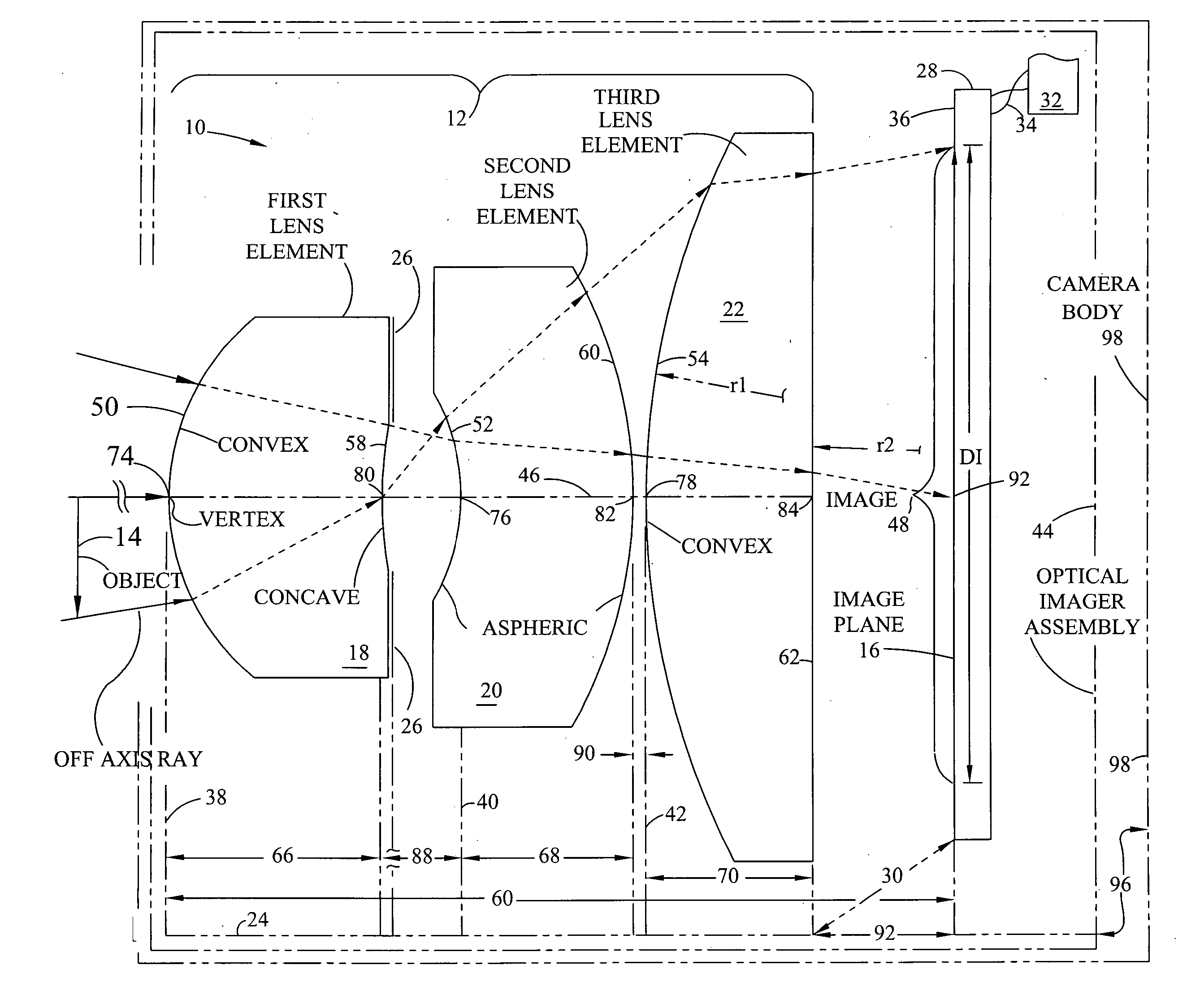
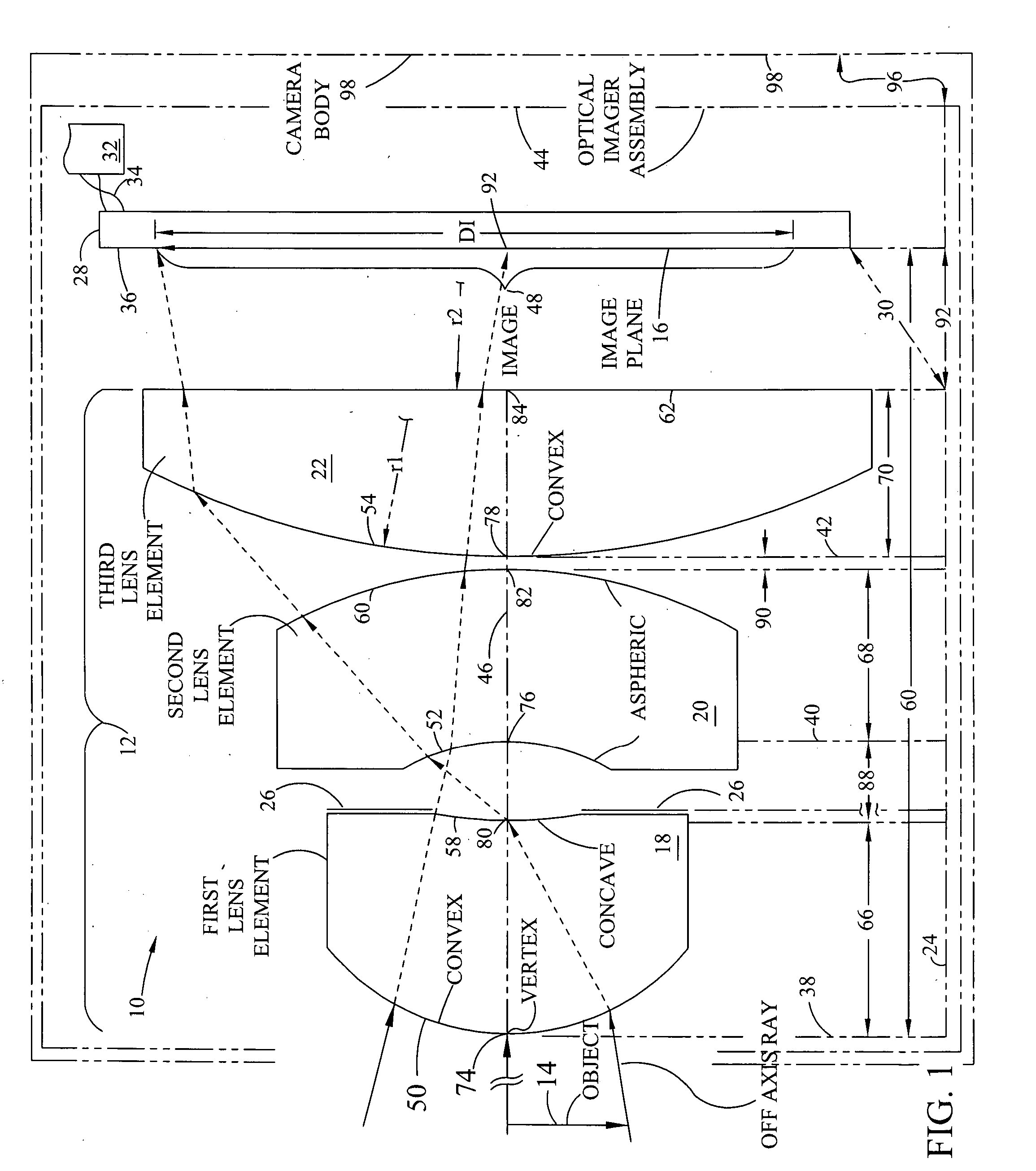
[0017]FIG. 1 shows the invention lens assembly 10 positioned under bracket 12 for forming the image of an object 14 on image plane 16. The lens assembly 10 comprises a first lens element 18, a second lens element 20 and a third lens element 22, each of which are coupled together and held in optical alignment by a lens frame or housing represented by phantom line 24. An aperture stop 26 is positioned between the first and second lens elements 18, 20.

[0018] An electronic imager 28 (either a CCD or CMOS imager) such as the Sony ICX098 CCD imager is represented by an elongated block at the right. The electronic imager 28 is coupled to and held in alignment with the lens assembly 10 by a first attachment link 30 to the lens frame or housing 24. Operation of the electronic imager 28 is supported by a camera electronics and a processor 32. Signal leads 34 schematically represent the cabling necessary to carry image signals, control levels and power from the electronic imager 28 to the cam...


PUM


Abstract

An lens assembly has a having a height TT and a focal length f0 and three lens elements with first and second surfaces, the first surface of each element facing the object. The first lens element has a positive power and a focal length f1. The second lens element 20 is a aspheric lens, the first surface being concave and facing the first lens element second surface. The second lens element second surface being an aspheric surface. The third lens element first surface is convex having a radius of r1 and the second surface having a radius r2 with |r2|>|r1|. The first, second and third lens elements are shaped are formed to obtain a ratio of f1 / f0 in the range of 0.5 to 2.0 and a TT / DI<1.5. The elements are formed and spaced to obtain an image with a maximum effective dimension DI on an image plane in a digital camera.

Description

FIELD OF THE INVENTION [0001] This invention relates to compact lenses for digital camera applications; in particular, for very compact digital cameras such as could be incorporated into a cellular telephone, personal digital assistant, or other very small electronic device. BACKGROUND OF THE INVENTION [0002] Digital cameras utilizing high-resolution electronic imaging sensors require high resolution optics. For the consumer market, it is important that the lenses can be produced in high volume inexpensively. For use in very compact digital cameras, and cameras that might be incorporated into devices such as palm-sized computers, cellular telephones and the like, the lens must be very compact. In particular, it must have a very short length from the lens front surface to the image plane. [0003] In the prior art, high resolution lenses have generally been made up of several individual lens elements in order to balance the inherent optical aberrations. These lenses that require a larg...

Claims


Application Information

Patent Timeline
Patent Type & Authority Applications(United States)
IPC IPC(8): G02B13/00
CPCG02B13/0035G02B13/001
Inventor NING, ALEX
Owner NING ALEX
Learn More