Rotary atomizing head type coating machine

a coating machine and atomizer technology, applied in the direction of liquid spraying plants, movable spraying devices, electric spraying apparatuses, etc., can solve the problems of reducing productivity and workability, and difficulty in effectively providing wash fluid to paint particles, so as to improve productivity and workability, and efficient wash the paint

Active Publication Date: 2017-05-11
ABB (SCHWEIZ) AG
View PDF1 Cites 13 Cited by
  • Summary
  • Abstract
  • Description
  • Claims
  • Application Information

AI Technical Summary

Benefits of technology

[0009]The configuration adopted by the present invention is characterized in that the rotary atomizing head is provided with an outer peripheral surface washing passage open onto the atomizing head outer peripheral surface for causing the wash fluid supplied from the feed tube to flow out into the annular clearance, and an outflow opening of the outer peripheral surface washing passage is provided in a position closer to the backside into the annular clearan

Problems solved by technology

However, since the rotary atomizing head is rotated at high speeds, the wash fluid having flowed out from the solvent passage tends to easily spread out to a radial outside by centrifugal forces.
Thereby, it is difficult to effectively supply the wash fluid to the paint particle having adh

Method used


Image

  • Rotary atomizing head type coating machine
  • Rotary atomizing head type coating machine
  • Rotary atomizing head type coating machine

Examples


first embodiment

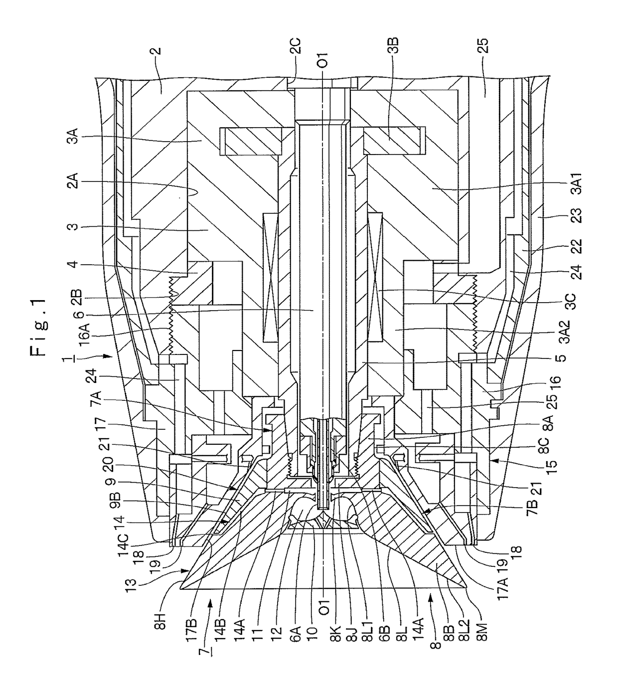
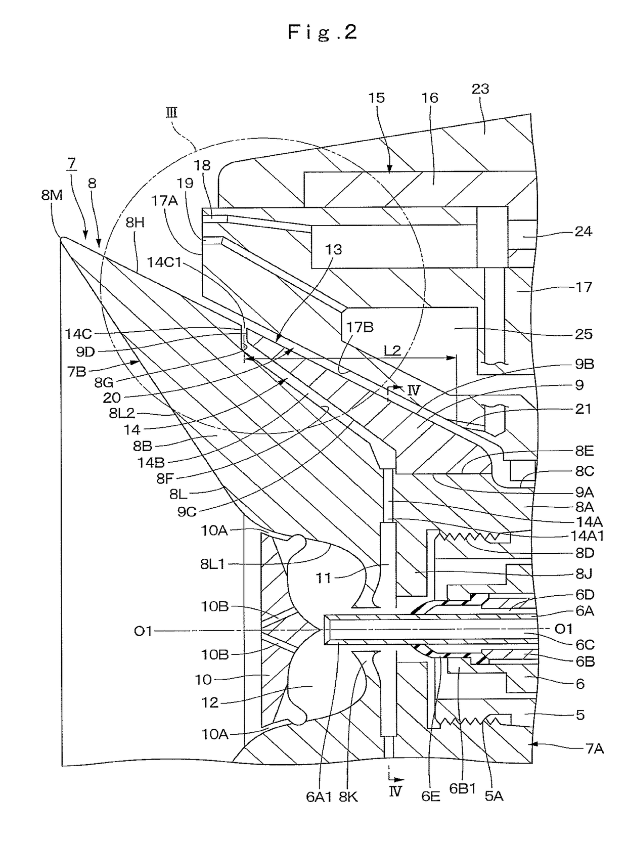
[0019]First, FIG. 1 to FIG. 4 show the present invention. The first embodiment will be explained by taking a rotary atomizing head type coating machine provided with a rotary atomizing head having a diameter dimension of approximately 70 mm, as an example.

[0020]In FIG. 1, a rotary atomizing head type coating machine 1 according to the first embodiment is configured as, for example, an electrostatic coating machine of a direct charging type that applies high voltages directly to paint by a high voltage generator (not shown). The rotary atomizing head type coating machine 1 is mounted to a tip end of an arm (not shown) of a paint coating robot, for example. The rotary atomizing head type coating machine 1 includes a housing 2, an air motor 3, a rotational shaft 5, a feed tube6, a rotary atomizing head 7, a shaping air ring 15 and an assist air spurting holes 21, which will be described later.

[0021]The housing 2 is mounted to the tip end of the arm in the paint coating robot at the bas...

second embodiment

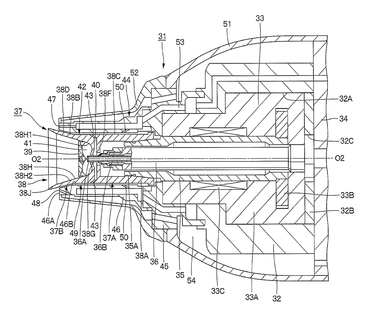
[0101]In FIG. 5, a rotary atomizing head type coating machine 31 is configured as a direct charging type electrostatic coating machine. The rotary atomizing head type coating machine 31 includes a housing 32, an air motor 33, a rotational shaft 35, a feed tube 36, a rotary atomizing head 37, a shaping air ring 44 and assist air spurting holes 50, which will be described later.

[0102]The housing 32 is provided therein with a motor accommodating part 32A. The motor accommodating part 32A is provided with an insertion hole 32C in a central position (position of an axis line O2-O2 of the rotational shaft 35 to be described later) of a bottom plate member 32B sealing the rear part for insertion and fit of the base end side of the feed tube 36 to be described later.

[0103]The air motor 33 is provided coaxially with the axis line O2-O2 within the motor accommodating part 32A in the housing 32. The air motor 33 rotates the rotational shaft 35 and the rotary atomizing head 37 to be described ...


PUM


Abstract

A rotary atomizing head (7) is provided with an outer peripheral surface washing passage (14) open onto anatomizing head outer peripheral surface (13) for causing wash fluid supplied from a feed tube (6) to flow out into an annular clearance (20) between the rotary atomizing head (7) and a shaping air ring (15). An outflow opening (14C1) of an outflow passage (14C) constituting the outer peripheral surface washing passage (14) is provided in a position closer to the backside into the annular clearance (20) by a length dimension (L1) than a front end surface (17A) of a front ring section (17) constituting the shaping air ring (15). Further, the outflow opening (14C1) opens to the annular clearance (20) in an angle (α1) that is an acute angle to the atomizing head outer peripheral surface (13).

Description

TECHNICAL FIELD[0001]The present invention relates to a rotary atomizing head type coating machine that sprays paint particles toward an object to be coated from a rotary atomizing head, for example.BACKGROUND ART[0002]In general, in a case of coating vehicle bodies of automobiles, articles of furniture, electrical appliances, and the like with paint, a rotary atomizing head type coating machine that is excellent in a coating efficiency and coating finish of paint is used. The rotary atomizing head type coating machine is provided with an air motor that uses compressed air as a power source, a hollow rotational shaft that is rotatably supported by the air motor and a tip end of which projects to a front side from the air motor, a feed tube that extends to the tip end of the rotational shaft through in the rotational shaft to supply paint or wash fluid, a rotary atomizing head a base end side of which is formed of a cylindrical section mounted to the tip end of the rotational shaft a...

Claims


Application Information

Patent Timeline
IPC IPC(8): B05B15/02B05B5/04B05B5/08B05B3/10
CPCB05B15/025B05B5/08B05B5/04B05B3/10B05B3/1014B05B5/0407B05B5/0415B05B5/0426B05B5/043B05B15/555B05B15/55
Inventor YAMAUCHI, KUNIHARU
Owner ABB (SCHWEIZ) AG
Why Eureka
Try Eureka