
Method for supplying plate elements to a machine, supply station and processing machine thus equipped

a technology of plate elements and processing machines, which is applied in the direction of de-stacking articles, thin material processing, and article separation, etc., can solve the problems of reducing the quality of the feeding operation, and not being desirable, and achieves the effect of compact supply stations

Active Publication Date: 2017-05-11
BOBST MEX SA
View PDF16 Cites 4 Cited by
  • Summary
  • Abstract
  • Description
  • Claims
  • Application Information

AI Technical Summary

Benefits of technology

The patent describes a storage and transfer device for plate elements that can separate them from an initial pile and save them for later use. The device has a displacement device that moves the plate elements simultaneously, ensuring they are properly aligned and organized. This allows for a more compact and streamlined supply station. The technical effect of this patent is a more efficient and organized storage and transfer system for plate elements.

Problems solved by technology

A first drawback is that the batch exerts a significant pressure force, primarily on the element at the bottom of the batch placed on the conveyor.
This pressure tends to crush these successive bottom elements and exert a stress, disturbing the conveyance of the element via the feeder, reducing the quality of the feeding operation and as a result the conveyance of the elements into the machine.
In other cases, the feeder inserts two elements at once instead of one at a time, which is not desirable.
Since the surfaces are able to be pre-printed or coated with a layer, for example a white color or other colors, they will be damaged by marks.
This makes the work of the operator particularly tiresome, for example when processing sheets of corrugated cardboard of large dimensions.
Moreover, such manual loading limits the capacity in terms of processing speeds.
Moreover, at rapid production rates, the batch of elements will reduce very rapidly and will require immediate restocking.
The interval between the transition from a first pile to the subsequent pile results in a discontinuous supply of elements.
Non-stop operation is not possible.
The total size requirement of the machine combined with its station becomes considerable.

Method used


Image

  • Method for supplying plate elements to a machine, supply station and processing machine thus equipped
  • Method for supplying plate elements to a machine, supply station and processing machine thus equipped
  • Method for supplying plate elements to a machine, supply station and processing machine thus equipped

Examples


Embodiment Construction

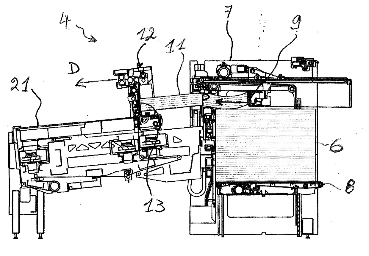
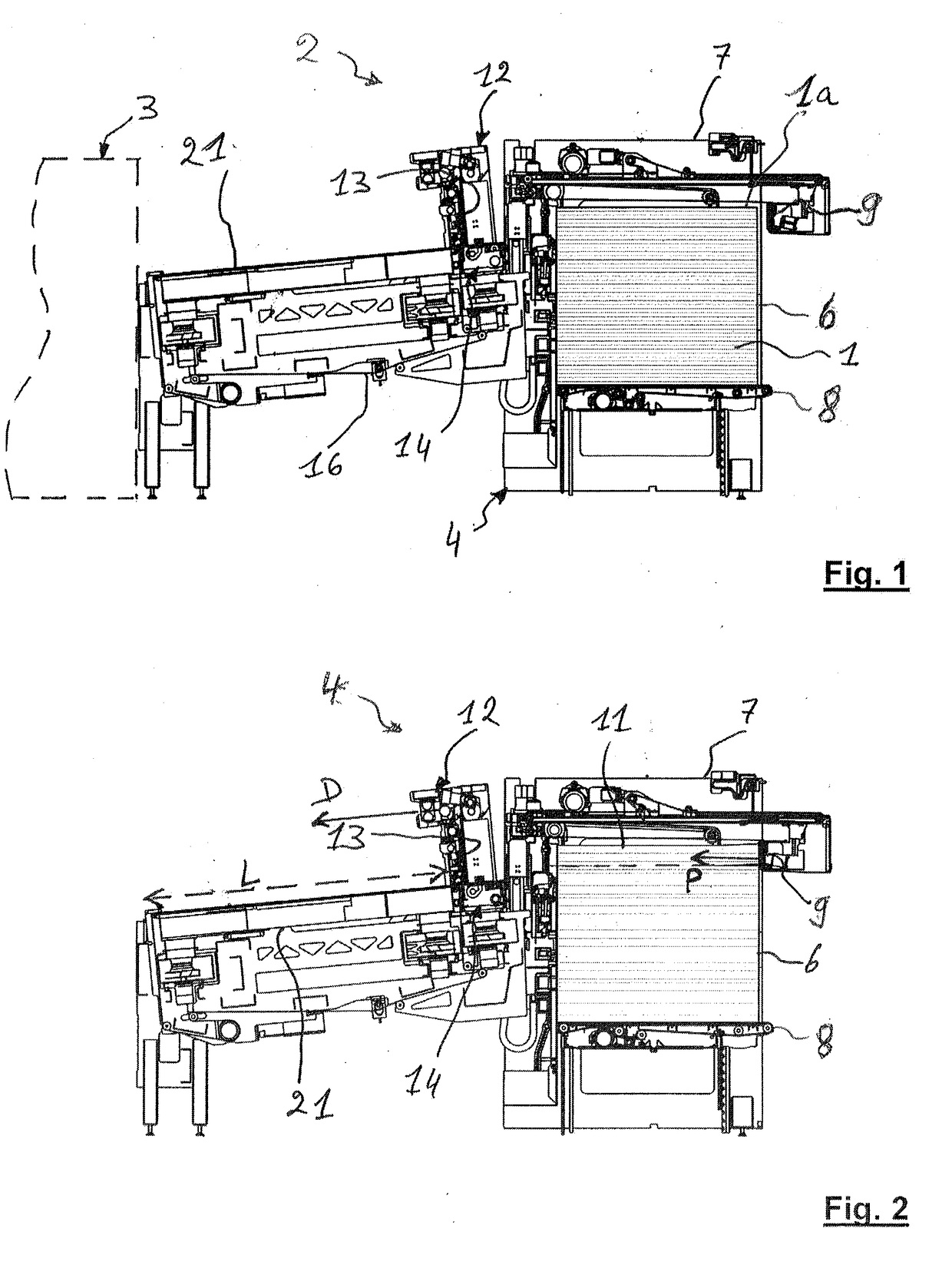
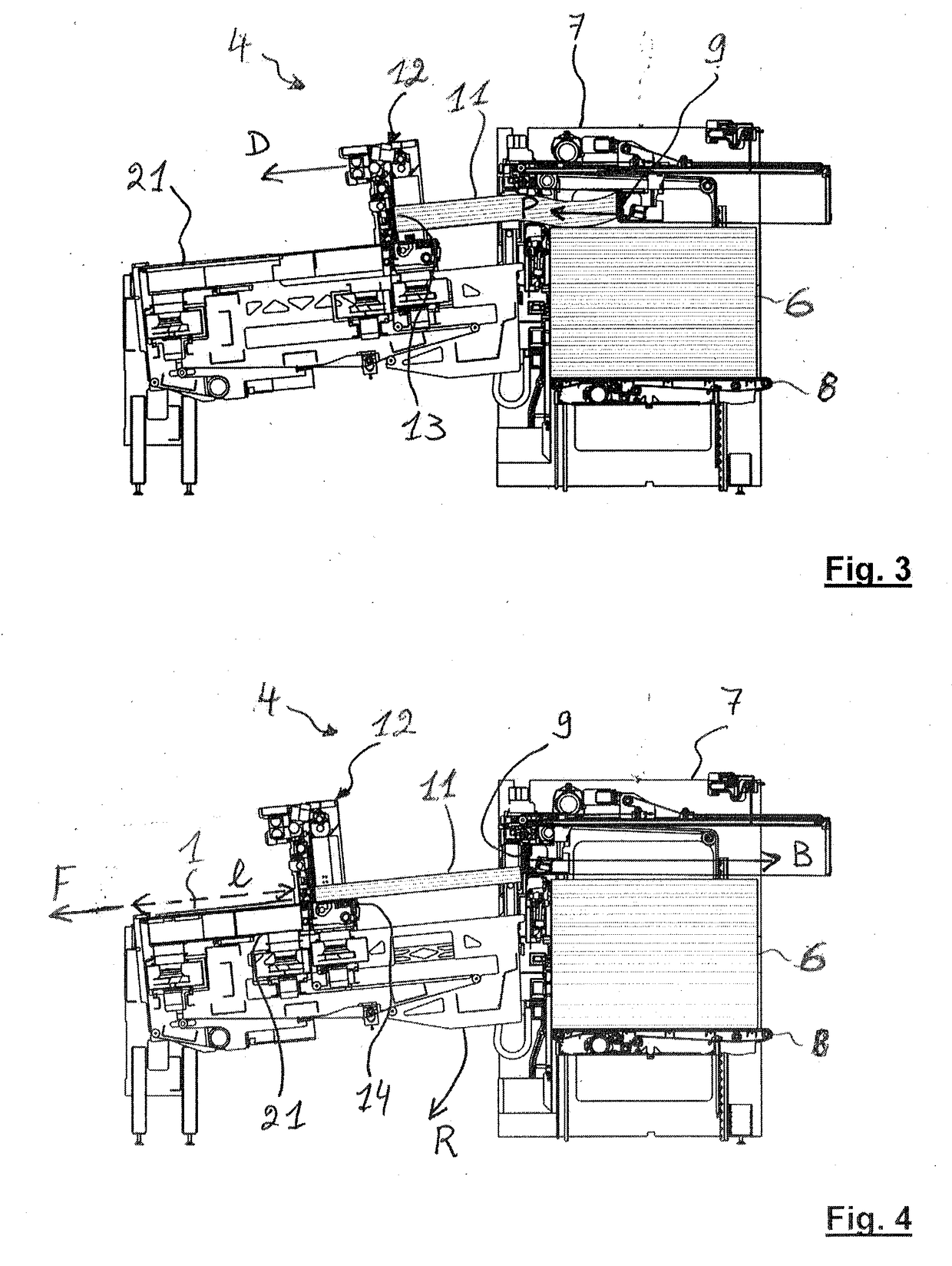
[0031]FIG. 1 illustrates a machine for processing plate elements, for example cardboard sheets 1, in the form of a digital inkjet printing machine 2. The printing machine 2 comprises a frame 3 (shown in dashed lines) and different printing units, such as inkjet printing heads placed in rows one after the other. The sheets 1 are processed by being printed. The sheets 1 are picked up, transported, circulate by passing at each of the heads through the printing machine 2, and emerge at a delivery station.

[0032]The machine for printing the sheets is advantageously provided with a supply station 4. This station 4 is mounted upstream of the printing machine 2 so as to supply the machine with sheets 1 at a high output. The median longitudinal axis of the station 4 is aligned with the median longitudinal axis of the machine 2. In the machine 2, a unit (not shown) for the lateral alignment of the sheets 1 may be arranged downstream of the supply station 4.

[0033]The sheets 1 firstly arrive in ...


PUM

PropertyMeasurementUnit
Lengthaaaaaaaaaa
Thicknessaaaaaaaaaa
Heightaaaaaaaaaa

Abstract

A method for supplying plate elements to a machine for processing the plate elements, from an initial pile of elements, the method includes: pushing a first batch of plate elements, from the top of the pile, downstream until the first batch comes at a storage capable of storing the first pushed batch, and simultaneously, displacing the storage downstream over a distance corresponding to the length of the first batch to separate the first batch from the pile; and thereafter transferring the elements of the first batch one after the other to the machine.

Description

CROSS-REFERENCE TO RELATED APPLICATIONS[0001]The present application is a 35 U.S.C. §§371 national phase conversion of PCT / EP2015 / 025038, filed Jun. 24, 2015, which claims priority of European Patent Application No. 14002202.1, filed Jun. 27, 2014, the contents of which are incorporated by reference herein. The PCT International Application was published in the French language.TECHNICAL FIELD[0002]The present invention relates to a method for supplying plate elements to a machine for processing plate elements. The invention also relates to a station for supplying plate elements to a machine for processing plate elements. The invention further relates to a machine for processing plate elements provided with such a station for supplying such plate elements.TECHNICAL BACKGROUND[0003]A processing machine, for example a machine for cutting or printing, is used in the packaging industry, for example to cut or print plate elements such as cardboard sheets. Said printed sheets then serve to...

Claims


Application Information

Patent Timeline
IPC IPC(8): B65G59/02
CPCB65G59/02B65G59/026B65H1/263B65H3/242B65H83/02B65H2301/4213B65H2701/176
Inventor CHIARI, MAUROCAZES, DANIEL
Owner BOBST MEX SA
Learn More