Defrosting device and refrigerator having the same

a technology of defrosting device and refrigerator, which is applied in the direction of defrosting, domestic cooling apparatus, application, etc., can solve the problems of increasing the temperature of the heat pipe, the defrosting may not be efficiently carried out for the lower cooling tube, etc., and achieves the effect of efficient defrosting

Active Publication Date: 2017-05-11
LG ELECTRONICS INC
View PDF8 Cites 8 Cited by
  • Summary
  • Abstract
  • Description
  • Claims
  • Application Information

AI Technical Summary

Benefits of technology

[0010]An aspect of the present disclosure is to provide a defrosting device capable of increasing the entire temperature of the heat pipe to perform efficient defrosting.

Problems solved by technology

Due to the flow of the working fluid, as working fluid transfers heat to the cooling tube, temperature may gradually decrease, and thus defrosting may not be efficiently carried out for a lower cooling tube.
In particular, considering that frost is mostly formed at a front side of the evaporator due to the flow of cool air, increasing the temperature of the heat pipe may be an important issue in defrosting reliability.

Method used


Image

  • Defrosting device and refrigerator having the same
  • Defrosting device and refrigerator having the same
  • Defrosting device and refrigerator having the same

Examples


first embodiment

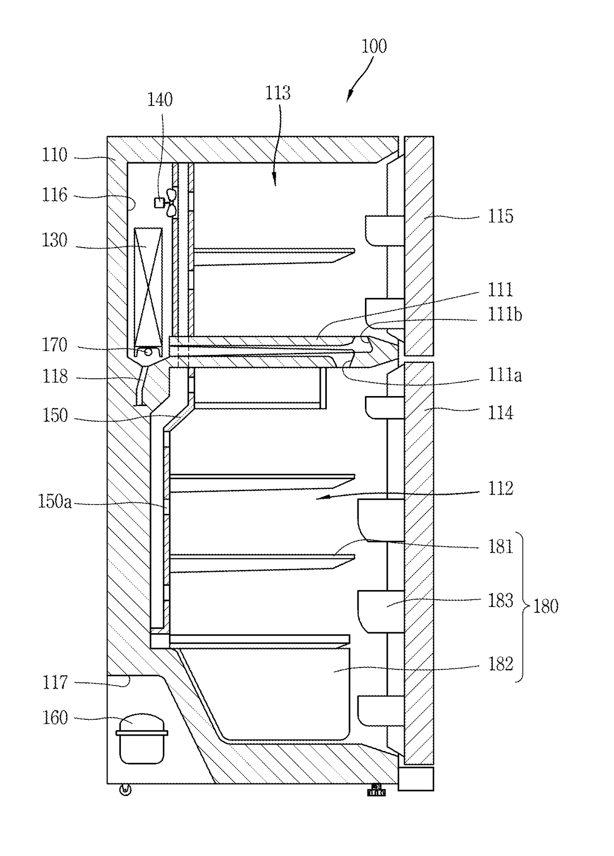
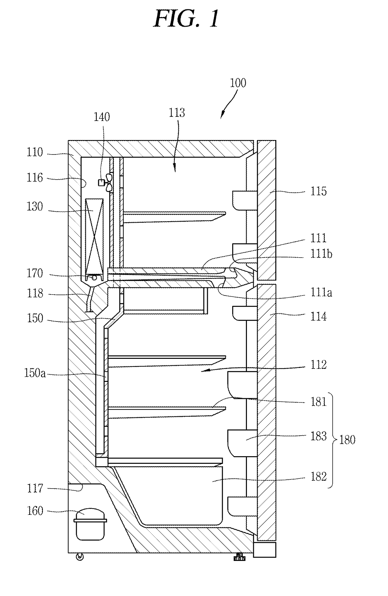
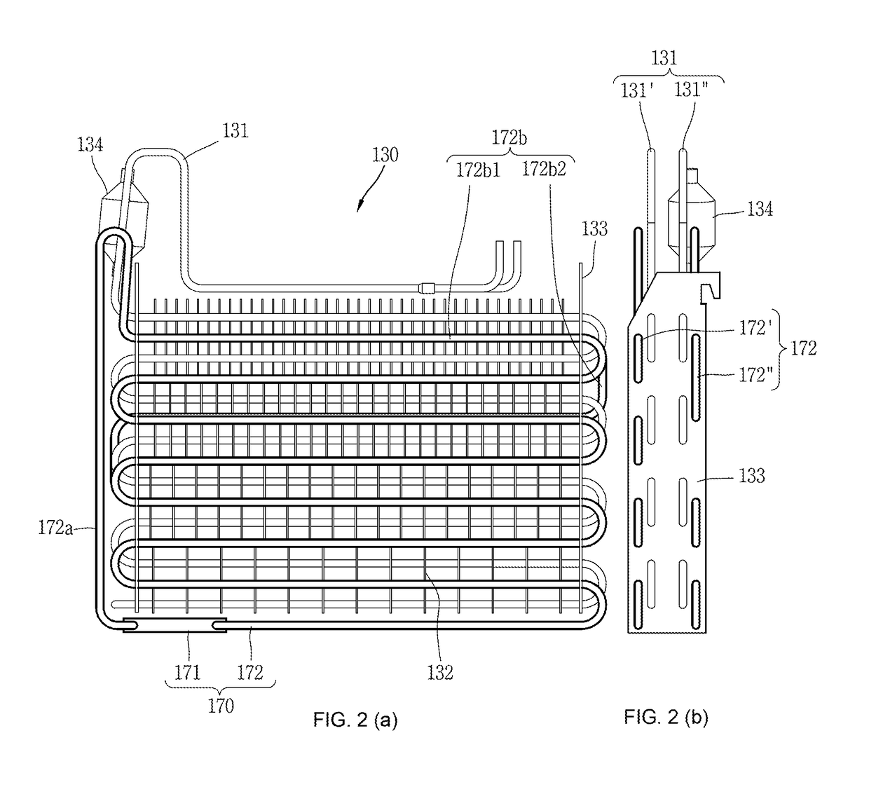
[0061]FIG. 2 is a front view (a) and a side view (b) illustrating an evaporator applied to the refrigerator of FIG. 1, and FIG. 3 is a conceptual view illustrating the layout of a first heat pipe and a second heat pipe in an evaporator illustrated in FIG. 2.

[0062]For reference, part of a second heat pipe 172″ overlaps with a first heat pipe 172′ and thus not seen in FIG. 2(a), but referring to FIG. 3, the entire shape of the second heat pipe 172″ is seen. In order to facilitate understanding, it is illustrated in FIG. 3 that part of the first cooling tube 131′ and second cooling tube 131″ is omitted.

[0063]Referring to FIGS. 2(a), 2(b), and 3, the evaporator 130 may include a cooling tube 131 (cooling pipe), a plurality of cooling fins 132, and support fixtures 133 at both sides.

[0064]The cooling tube 131 is repeatedly bent in a zigzag shape to constitute a plurality of columns, and refrigerant is filled therein. The cooling tube 131 may be formed in an aluminum material.

[0065]The co...

second embodiment

[0208]FIG. 11 is a front view (a) and a side view (b) illustrating an evaporator 330 applied to the refrigerator 100 of FIG. 1, and FIG. 12 is a conceptual view illustrating the layout of a first heat pipe 371′ and a second heat pipe 371″ in the evaporator 330 illustrated in FIG. 11.

[0209]According to the present example, a total number of columns of the first heat pipe 372′ disposed on a front portion of the evaporator 330 may be configured to be less than that of the second heat pipe 372″. Here, the total number of columns denotes a total number of columns formed by a plurality of horizontal tubes 372b1 on a heat emitting part 372b constituting a heat pipe 372.

[0210]According to the foregoing structure, a path through which working fluid (F) circulates may be shorter to allow the temperature of the first and the second heat pipe 372′, 372″ to increase as a whole, and a total number of columns of the second heat pipe 372″ may be larger than that of the first heat pipe 372′ to trans...


PUM


Abstract

The present disclosure discloses a defrosting device, including a heating unit provided at a lower side of an evaporator, and configured to heat working fluid therein; and a plurality of heat pipes, both end portions of which are connected to an inlet and an outlet of the heating unit, respectively, and at least part of which are disposed adjacent to a cooling tube of the evaporator to emit heat to the cooling tube due to high temperature working fluid heated and transferred by the heating unit, wherein the plurality of heat pipes are configured with a first heat pipe and a second heat pipe disposed to form two rows on a front portion and a rear portion of the evaporator, respectively, and the first heat pipe and the second heat pipe are formed in different lengths.

Description

CROSS-REFERENCE TO RELATED APPLICATIONS[0001]Pursuant to 35 U.S.C. §119(a), this application claims the benefit of earlier filing date and right of priority to Korean Application No. 10-2015-0158325, filed on Nov. 11, 2015, the contents of which is incorporated by reference herein in its entirety.BACKGROUND OF THE INVENTION[0002]1. Field of the Invention[0003]The present disclosure relates to a defrosting device for removing frost formed on an evaporator provided in a refrigeration cycle, and a refrigerator having the same.[0004]2. Description of the Related Art[0005]An evaporator provided in a refrigeration cycle decreases ambient temperature using cool air generated by the circulation of coolant flowing through a cooling tube. During the process, when there occurs a temperature difference from ambient air, a phenomenon of condensing and freezing moisture in the air on a surface of the cooling tube occurs.[0006]A defrosting method using an electric heater has been used for a defros...

Claims


Application Information

Patent Timeline
Patent Type & Authority Applications(United States)
IPC IPC(8): F25D21/06F25D21/12F25D11/02F25D21/08
CPCF25D21/06F25D21/08F25D2321/147F25D11/02F25D2321/1413F25D21/12F28F19/006F28D1/0477F28D15/0266F25B2400/01F28F2210/04F28F17/00F28F1/32F28F2275/06F28F2215/04F25D21/125F25D21/065F25D21/10
Inventor SHIN, YOUNGJAEJUNG, KWANGSOOKANG, WOOCHEOLLEE, GEUNHYUNG
Owner LG ELECTRONICS INC
Why Eureka
Try Eureka