
Monolithic element and system for collimating or focusing laser light from or to an optical fiber

a monolithic optical element and laser light technology, applied in the field of optical systems, can solve the problems of impracticality of adapting to optical measurement probe design without major investment in custom grin lens design and fabrication, and achieve the effect of reducing mechanical stress concentration

Active Publication Date: 2017-05-11
ENDRESS + HAUSER OPTICAL ANALYSIS INC
View PDF23 Cites 0 Cited by
  • Summary
  • Abstract
  • Description
  • Claims
  • Application Information

AI Technical Summary

Benefits of technology

The patent describes an optical element that can either collimate or focus light from a fiber. This is useful in situations where there is a risk of high energy density light coming in contact with combustible gases or contaminants. The optical element is designed to have a curved surface with the same radius of curvature, or a different radius of curvature to minimize mechanical stress concentration. The length and refractive index of the optical element are also chosen to achieve perfect collimation or focusing of collimated light. This design helps to keep the fiber in contact with the optical element and ensures the absence of high energy density light in any gaps.

Problems solved by technology

However, commonly available GRIN materials and lenses are only available in a very limited range of diameters, focal lengths and numerical apertures, making their adaptation to optical measurement probe designs impractical without major investment in custom GRIN lens design and fabrication.

Method used


Image

  • Monolithic element and system for collimating or focusing laser light from or to an optical fiber
  • Monolithic element and system for collimating or focusing laser light from or to an optical fiber
  • Monolithic element and system for collimating or focusing laser light from or to an optical fiber

Examples


Embodiment Construction

[0015]This invention broadly uses a monolithic optic element to collimate or focus from / to an optical fiber with multiple advantages, including:

[0016]1) the elimination of high energy density hot spots and the components and assembly steps required for sealing and / or purging;

[0017]2) the elimination of various optical components as well as the machining required to hold and position such components in a housing; and

[0018]3) a dramatic reduction in the requirements for axial and lateral alignment of the fiber relative to the monolithic optic element, thereby simplifying fiber locating and relocating procedures.

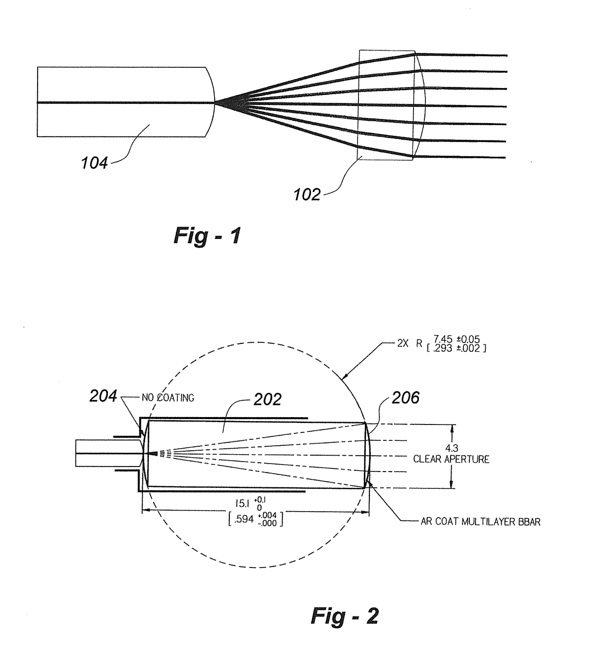
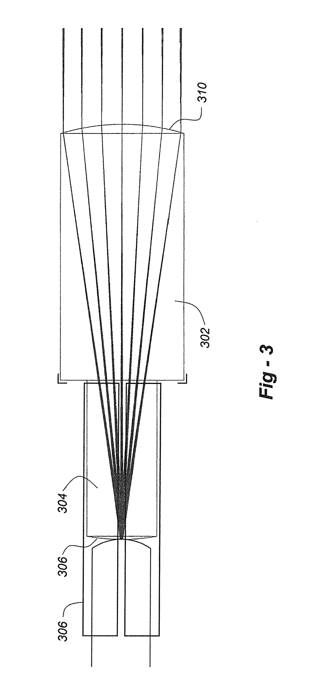
[0019]FIG. 2 is a simplified diagram illustrating a basic embodiment of the invention in a light collimating configuration. The monolithic optic element 202 in this case may be a standard barrel or ‘drum’ lens, defined as a cylindrical plug taken from a glass sphere indicated by the broken-line circle. Such a sphere section produces most accurate collimation / focusing of a conta...


PUM


Abstract

A monolithic optical element and system is used for collimating or focusing laser light from or to optical fibers. The optical fiber terminates in a tip that directly abuts against the first surface of the optical element. The optical element may provide a collimation or focusing function depending upon whether the abutting fiber delivers light for collimation or receives focused light from a collimated beam. The optical element may be a standard or modified barrel or drum lens, with the first and second surfaces being convex curved surfaces having the same or different radii of curvature. The end of the optical element to which the fiber abuts may have a diameter to match the inner diameter of a ferrule for positioning the fiber. A pair of the elements may be used for collimation and focusing in a Raman probehead or other optical detection system.

Description

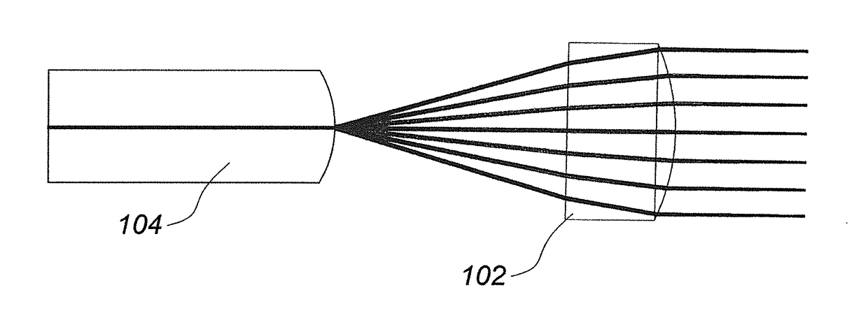
CROSS-REFERENCE TO RELATED APPLICATION[0001]The present application is a divisional application of U.S. patent application Ser. No. 14 / 455,235, filed on Aug. 8, 2014, the entire contents of which are incorporated herein by reference.TECHNICAL FIELD[0002]This invention relates generally to optical systems and, in particular, to a monolithic optical element and system for collimating or focusing laser light from or to optical fibers in a Raman or other optical measurement probe, for example.BACKGROUND[0003]FIG. 1 is a simplified schematic diagram illustrating imaging optics used to collimate the light from an optical fiber 104. As is typical, the distal end of the fiber is spaced apart from the surface of lens 102 used for collimation. Not only does this arrangement require precise mechanical locating (and re-locating) to laterally and axially align the fiber relative to the lens, if the fiber is carrying high-power laser light, as might be the case with Raman probes, this results in ...

Claims


Application Information

Patent Timeline
Patent Type & Authority Applications(United States)
IPC IPC(8): G02B6/32G01J3/44G01J3/02G02B6/42G02B6/36
CPCG02B6/32G02B6/4201G01J3/44G01J3/0208G01J3/0218G02B6/3624G02B6/3869G01J3/0205G01J3/024G02B6/322G02B3/0087G02B3/02
Inventor TEDESCO, JAMES M.
Owner ENDRESS + HAUSER OPTICAL ANALYSIS INC
Learn More