Optimisation of the bearing points of the stilts of vanes in a method for machining said vanes

a technology of bearing points and stilts, which is applied in the field of optimisation of bearing points of stilts of vanes in a method of machining said stilts, can solve the problems of difficult to maximize the distance between bearing points, long and expensive fabrication using a foundry process, and particularly complex blade parts, so as to minimize mechanical stress concentration, reduce the effect of weight and reducing the amount of was

Inactive Publication Date: 2014-12-18
SN DETUDE & DE CONSTR DE MOTEURS DAVIATION S N E C M A
View PDF8 Cites 5 Cited by
  • Summary
  • Abstract
  • Description
  • Claims
  • Application Information

AI Technical Summary

Benefits of technology

[0005]A main object of the present invention is thus to mitigate such drawbacks by proposing a method of machining blades that makes it possible in particular to minimize concentrations of mechanical stresses while also saving weight.
[0007]By limiting stress concentrations on the blade, this combination of the support function and of the bearing point function makes it possible to simplify the machining that is to be performed, and also to obtain the desired saving in weight.

Problems solved by technology

In known manner, blades are parts that are particularly complex and for which fabrication using a foundry process is lengthy and expensive and found to be difficult, in particular because of the fabrication tolerances that are required.
Unfortunately, in order to execute the machining operations, it is necessary to select a system for positioning the part in the machining center that is optimized and that guarantees the required accuracy while also being easy to inspect.
Unfortunately, the moving blades of turbines, for example, are generally of small dimensions, which makes it difficult to maximize the distances between the bearing points, particularly when the bearing points of non-zero size give rise to extra weight.

Method used


Image

  • Optimisation of the bearing points of the stilts of vanes in a method for machining said vanes
  • Optimisation of the bearing points of the stilts of vanes in a method for machining said vanes

Examples


Embodiment Construction

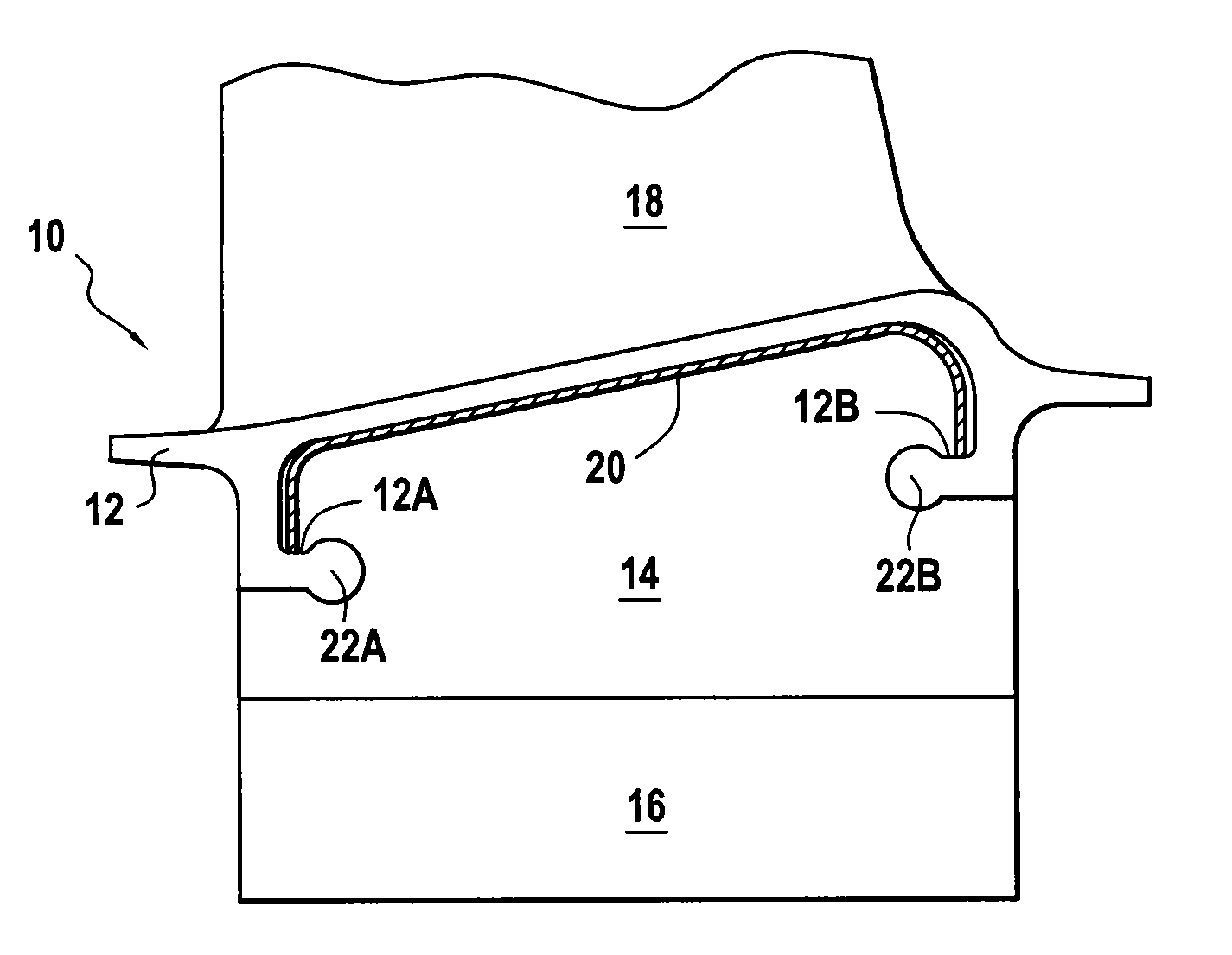
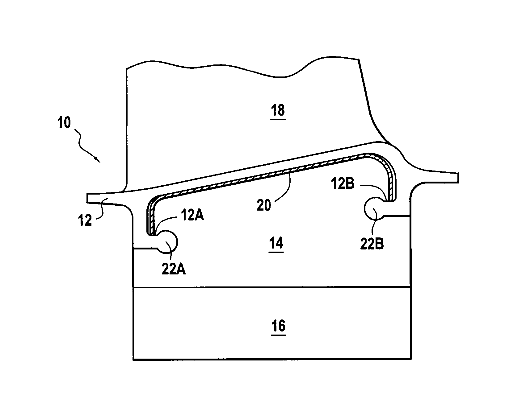
[0011]The sole FIGURE is an elevation view of a turbine engine blade 10, e.g. a fan blade, a turbine blade, or a compressor blade, that is fastened in known manner to the periphery of a rotor disk of the engine (not shown) and that typically comprises a blade root 16 of a Christmas tree or dovetail shape under a platform 12, and spaced apart therefrom by a stilt 14, which root is received in a corresponding slot or groove (not shown) in the periphery of the rotor disk.

[0012]The stilt 14 presents thickness that is small compared to the blade root 16 so as to pass through the opening defined by the slot and provide mechanical connection between the root and the aerodynamic portion (or airfoil 18) of the blade. Under the platform there are conventionally arranged both upstream and downstream supports 12A and 12B for a sealing liner 20, where “upstream” and “downstream” are relative to the stream of air passing between the blades.

[0013]In order to enable such a blade to be machined, it ...


PUM

PropertyMeasurementUnit
weightaaaaaaaaaa
distancesaaaaaaaaaa
dimensionsaaaaaaaaaa

Abstract

A method of machining a blade in a three-dimensional machining center, the blade including an airfoil, a platform including upstream and downstream supports formed respectively under the upstream and downstream portions thereof for supporting a sealing liner, a blade root, and a stilt interposed between the platform and the blade root, the method including the upstream and downstream supports constituting two bearing points for a six-point positioning system for positioning the blade in the three-dimensional machining center.

Description

BACKGROUND OF THE INVENTION[0001]The present invention relates to the general field of gas turbines for airplane or helicopter engines and it relates more particularly to a method of fabricating blades, which method serves to minimize stresses and weight during machining.[0002]In known manner, blades are parts that are particularly complex and for which fabrication using a foundry process is lengthy and expensive and found to be difficult, in particular because of the fabrication tolerances that are required.[0003]Because of its dimensional tolerances that are of millimeter order and because of its surface state, a casing is rarely a part that can be used directly. It must therefore subsequently be machined at least in part (typically on a numerically controlled machining center), which makes it necessary to have recourse to a geometrical frame of reference that is specific to such machining. Unfortunately, in order to execute the machining operations, it is necessary to select a sy...

Claims


Application Information

Patent Timeline
Patent Type & Authority Applications(United States)
IPC IPC(8): F01D5/14B23P15/02
CPCB23P15/02F01D5/14B23Q3/063F05D2230/68F01D5/147F01D11/008F05D2240/306F05D2230/10Y10T29/49336Y02T50/60
Inventor HANSOM, MICHAELTRAN, HUU-THANHBARIAUD, CHRISTIAN
Owner SN DETUDE & DE CONSTR DE MOTEURS DAVIATION S N E C M A
Why Eureka
Try Eureka