
System for predicting induced seismicity potential resulting from injection of fluids in naturally fractured reservoirs

a technology of induced seismicity and prediction model, which is applied in the field of geomechanical modeling, can solve the problems of increasing occurrence, increasing the weight of the overburden, and activities giving rise to vertical and horizontal stresses that create natural fractures, and achieves the effect of quick yield

Active Publication Date: 2017-05-11
FRACGEO LLC
View PDF4 Cites 11 Cited by
  • Summary
  • Abstract
  • Description
  • Claims
  • Application Information

AI Technical Summary

Benefits of technology

The present invention is a system that can create a model of natural fractures in a way that takes into account the continuous representation of the fractures from multiple sources. This model can be used to predict the future behavior of the fractures and can also incorporate discrete fault lines. The modeling is done using a unique method that uses particles to represent the fractures, and this method can quickly produce important information about the stress on the fractures that can affect seismicity. Overall, this invention provides a faster and more accurate way to predict the future behavior of natural fractures, which can be beneficial in the energy industry and other areas.

Problems solved by technology

Such injections, especially of high volumes and in certain stratigraphic units, have recently been linked to the increasing occurrence of earthquakes.
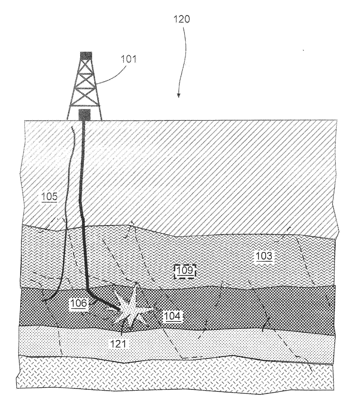
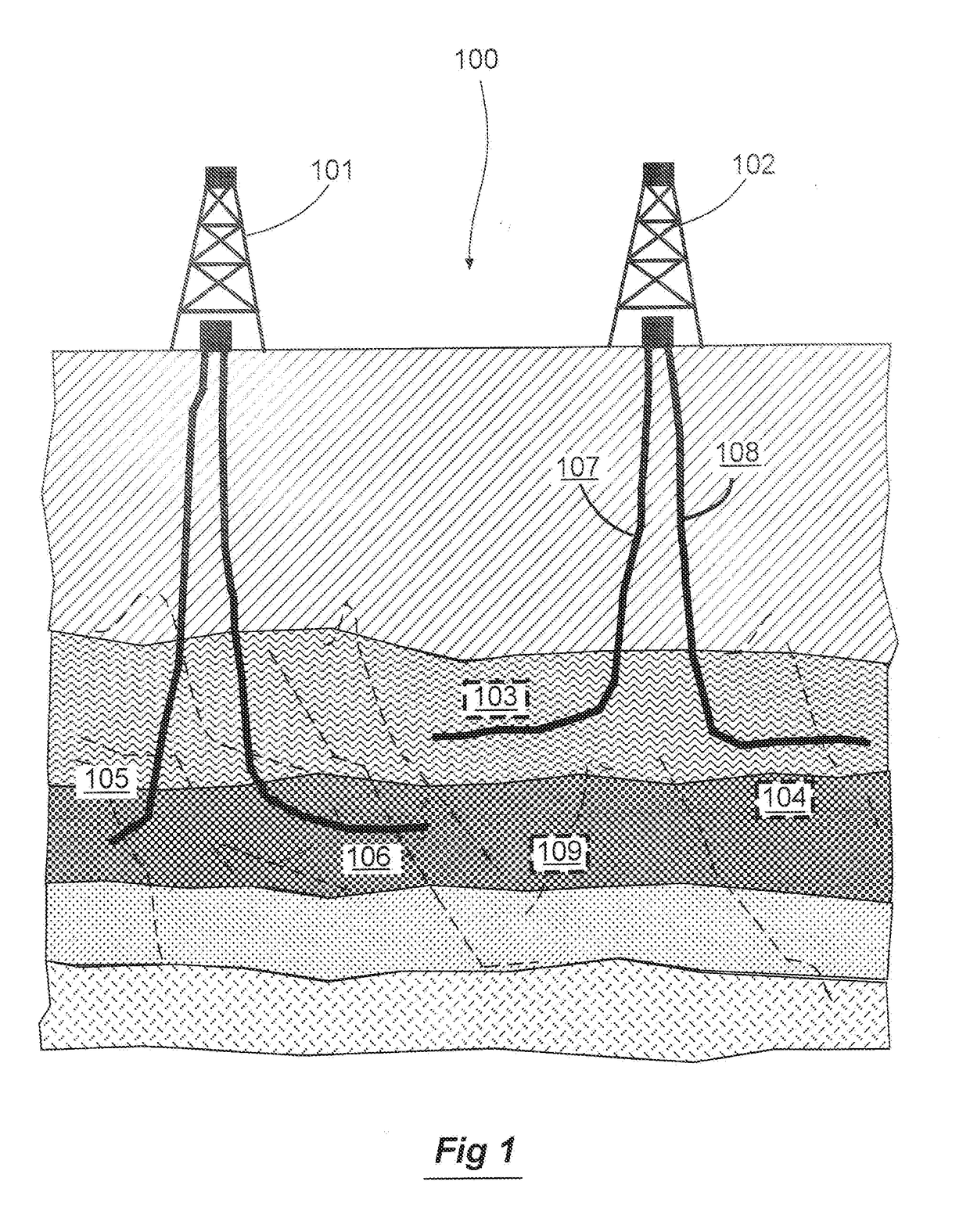
In a subterranean reservoir, the weight of the overburden and most often tectonic activities gives rise to vertical and horizontal stresses that create natural fractures.
When injection of fluids is initiated in a wellbore in this heterogeneous stress field perturbed by the natural fractures, there is probability to induce a large seismic event.
However, the actual modeling of the interactions between regional fault systems and stresses with these pressures has been absent.
Unfortunately, most of these computational methods do not use a realistic description of the natural fractures driven by geophysical and geologic constraints, and do not account for the multitude of interactions which occur between multiple fractures and the stress fields.
As a result the current computational methods taken separately are not able to predict either microseismicity or large-scale seismic events.
This lack of a mechanistic model that is able to be validated with microseismic or seismic data, hampers the ability to predict the mechanical effects of large-scale underground injection and other similar practices which may alter existing stress fields.
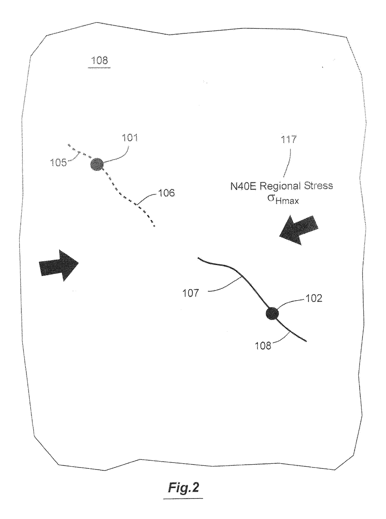
Foremost among the deficiencies of the current methods is their inability to seamlessly input, prior to any simulation of injection, the proper initial geomechanical conditions that are the result of the interaction between the regional stress, pore pressure, and the natural fractures.
As a result of these technical challenges, conventional modeling technologies and software have been unable to provide the necessary information needed to prevent the occurrence of destructive earthquakes induced by high volume injections that are used in water disposal and hydraulic fracturing.
One possible cause of the poor placement of the water disposal wellbores and completion stages is the unavailability of technologies that allow the rapid identification and mapping of geomechanical sweet spots where the wells should be drilled and injection volumes selected.
Although logging tools can be very useful, they are of limited use once the well is drilled since the driller cannot change its position if it encounters many areas of high differential stress that will not provide successful completion stages or safe zones for water disposal.

Method used


Image

  • System for predicting induced seismicity potential resulting from injection of fluids in naturally fractured reservoirs
  • System for predicting induced seismicity potential resulting from injection of fluids in naturally fractured reservoirs
  • System for predicting induced seismicity potential resulting from injection of fluids in naturally fractured reservoirs

Examples


Embodiment Construction

[0027]For the purposes of promoting an understanding of the principles of the present invention, reference will now be made to the embodiments illustrated in the drawings, and specific language will be used to describe the same. It is nevertheless understood that no limitation to the scope of the disclosure is intended. Any alterations and further modifications to the described methods, devices, and systems, and any further application of the principles of the present disclosure are fully contemplated and included within the present disclosure as would normally occur to one skilled in the art to which the disclosure relates. In particular, it is fully contemplated that the steps, features or components described with respect to one embodiment may be combined with the steps, features or components described with respect to other embodiments of the present disclosure. For the sake of brevity, however, the numerous iterations of these combinations will not be described separately.

[0028...


PUM


Abstract

A method for minimizing the risk of induced seismicity from injection of fluids into a naturally fractured reservoir uses a meshless particle-based simulation to quantify the heterogeneity in energy storage within the reservoir. In particular, this methodology creates an equivalent fracture model from data on the natural fracture density, regional stress, pore pressure and elastic properties of the reservoir, in which points in the reservoir have a fracture length and fracture orientation. A meshless particle-based method is then employed to simulate the geomechanical interaction between regional stress and natural fractures to estimate the stress anisotropy and strain (e.g., differential stress and shear strain). The induced seismicity potential is then calculated at points in the reservoir based on the estimated stress anisotropy and strain. A zone for injection of fluids into the reservoir can be selected by identifying a large area of the reservoir having low induced seismicity potential.

Description

RELATED APPLICATION[0001]The present application is based on and claims priority to the Applicant's U.S. Provisional Patent Application 62 / 291,618, entitled “System for Predicting Induced Seismicity Potential Resulting from Injection of Fluids in Naturally Fractured Reservoirs,” filed on Feb. 5, 2016. The present application is also a continuation-in-part of the Applicant's co-pending U.S. patent application Ser. No. 15 / 045,861, entitled “System For Hydraulic Fracturing Design And Optimization In Naturally Fractured Reservoirs,” filed on Feb. 17, 2016, which is based on and claims priority to U.S. Provisional Patent Application 62 / 207,569, filed on Aug. 20, 2015.BACKGROUND OF THE INVENTION[0002]Field of the Invention. The present invention relates generally to the field of geomechanical modeling. More specifically, the present invention discloses a system for an induced seismicity prediction model to be used when fluids are injected in naturally fractured reservoirs for the purpose ...

Claims


Application Information

Patent Timeline
IPC IPC(8): G06F17/50E21B43/26G06F17/11E21B41/00
CPCG06F17/5009E21B41/0092E21B49/00G06F17/11E21B7/046E21B43/26G06F2111/10G06F30/20G06F30/25
Inventor UMHOLTZ, NICHOLAS MOEHLEOUENES, AHMED
Owner FRACGEO LLC
Learn More