
Data processing apparatus and method for powering down a cache

a data processing apparatus and cache technology, applied in the direction of memory adressing/allocation/relocation, instruments, sustainable buildings, etc., can solve the problems of difficult to achieve using current techniques, difficult and inability to provide two such separate caches. , to achieve the effect of reducing the size and complexity of the degree of dirty checking circuitry and achieving faster outpu

Inactive Publication Date: 2013-02-07
RGT UNIV OF MICHIGAN +1
View PDF4 Cites 28 Cited by
  • Summary
  • Abstract
  • Description
  • Claims
  • Application Information

AI Technical Summary

Benefits of technology

This patent is about a circuit that helps determine the level of dirt in a cache, and uses that information to decide which parts of the cache to power down. The circuit makes this determination by using a dirty way indication, which helps to prioritize which parts of the cache to power down. The circuit can also use an approximation function to estimate the total number of dirty fields in the cache, which can be useful in some cases. Overall, this approach makes the circuit faster and more power efficient, and helps improve the performance of the cache.

Problems solved by technology

However, the time taken to power down a cache can be significant, particularly where cache lines contain dirty data and accordingly it is necessary to perform a clean and invalidate operation in order to flush the valid and dirty data to a lower level of the memory hierarchy.
To achieve the maximum energy saving from powering down a cache in such circumstances, it is beneficial if the energy consumption of the cache can be reduced as quickly as possible, and this is often difficult to achieve using current techniques.
However, in many systems, it is not practical to provide two such separate caches.
It does however make the cache much dirtier.

Method used


Image

  • Data processing apparatus and method for powering down a cache
  • Data processing apparatus and method for powering down a cache
  • Data processing apparatus and method for powering down a cache

Examples


Embodiment Construction

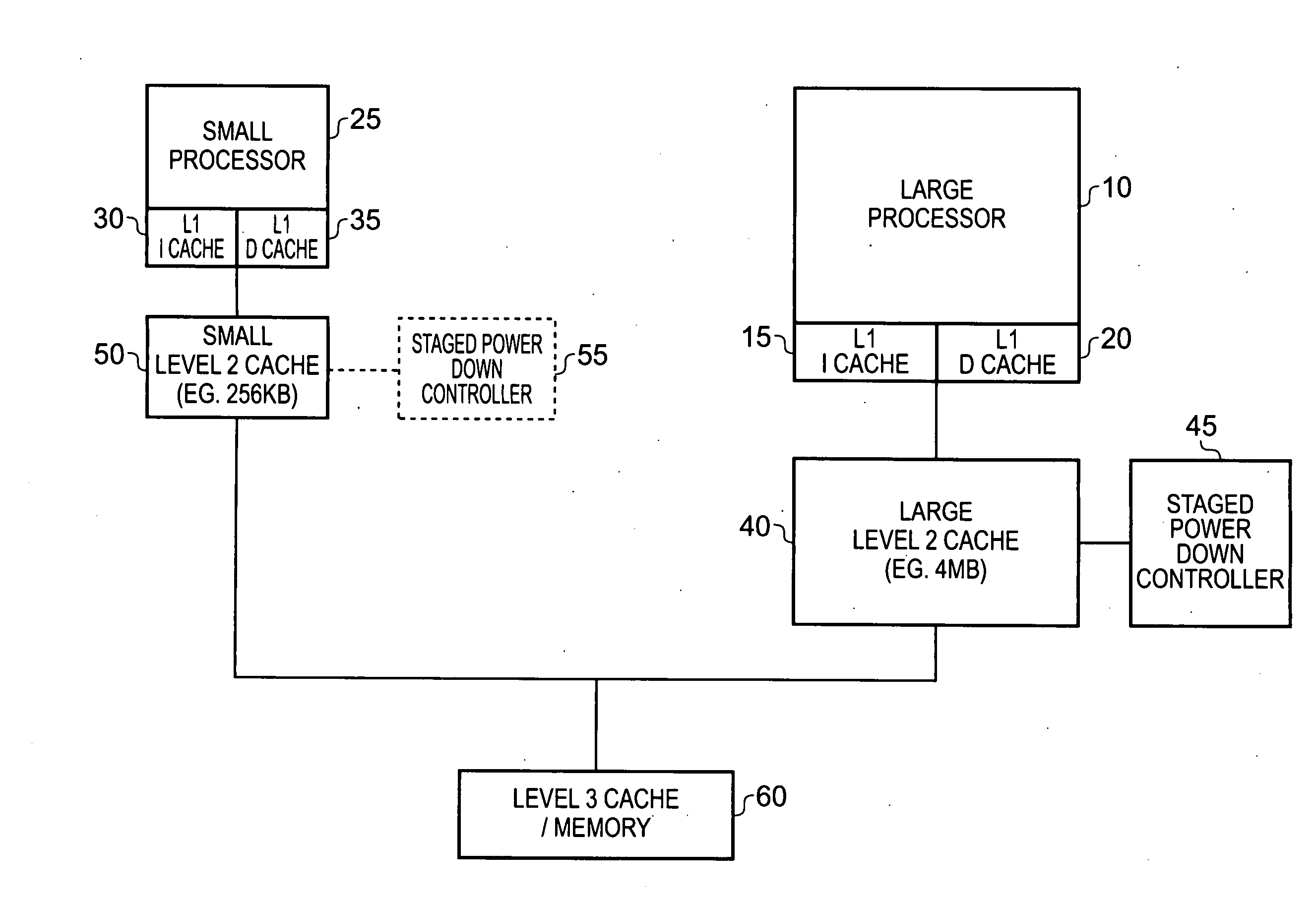
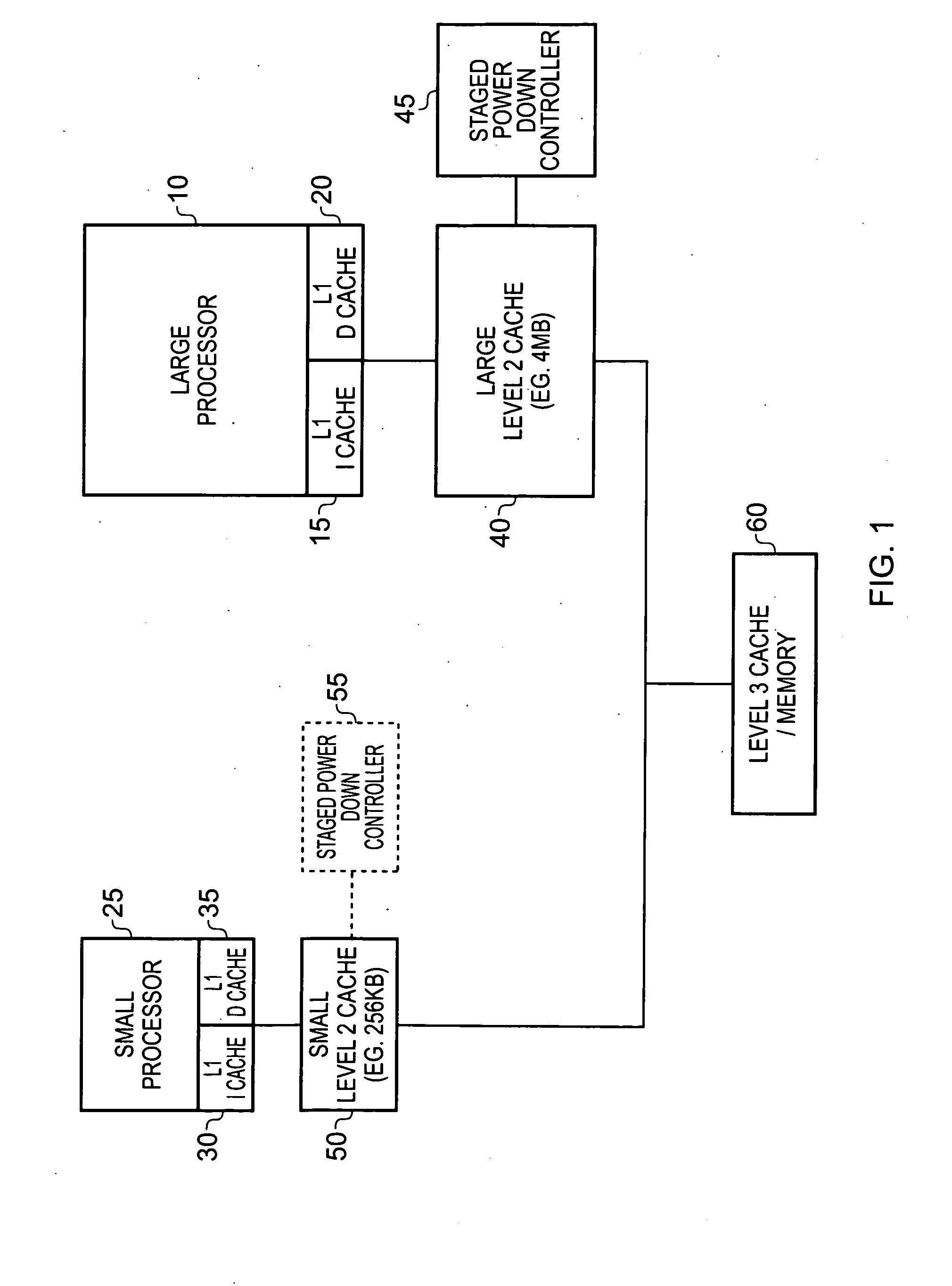
[0058]FIG. 1 is a block diagram of a data processing system in accordance with one embodiment. The system includes a relatively small, relatively low energy consumption, processor 25 (hereafter referred to as the small processor) and a relatively large, relatively high energy consumption, processor 10 (hereafter referred to as the large processor). During periods of high workload the large processor 10 is used and the small processor 25 is shut down, whilst during periods of low workload, the small processor 25 is used and the large processor 10 is shut down.

[0059]Both processors 10, 25 have their own associated level 1 (L1) instruction cache 15, 30 and L1 data cache 20, 35. In addition, both processors have their own level 2 (L2) caches, the large processor 10 having a relatively large L2 cache 40 whilst the small processor 25 has a relatively small L2 cache 50. In accordance with the illustrated embodiment, the L2 cache 40 has staged power down control circuitry 45 associated ther...


PUM


Abstract

A data processing apparatus is provided comprising a processing device, and an N-way set associative cache for access by the processing device, each way comprising a plurality of cache lines for temporarily storing data for a subset of memory addresses of a memory device, and a plurality of dirty fields, each dirty field being associated with a way portion and being set when the data stored in that way portion is dirty data. Dirty way indication circuitry is configured to generate an indication of the degree of dirty data stored in each way. Further, staged way power down circuitry is responsive to at least one predetermined condition, to power down at least a subset of the ways of the N-way set associative cache in a plurality of stages, the staged way power down circuitry being configured to reference the dirty way indication circuitry in order to seek to power down ways with less dirty data before ways with more dirty data. This approach provides a particularly quick and power efficient technique for powering down the cache in a plurality of stages.

Description

BACKGROUND OF THE INVENTION[0001]1. Field of the Invention[0002]The present invention relates to a data processing apparatus and method for powering down a cache.[0003]2. Description of the Prior Art[0004]A cache may be arranged to store data and / or instructions fetched from a memory so that they are subsequently readily accessible by a processing device having access to that cache, for example a processor core with which the cache may be associated. Hereafter, the term “data value” will be used to refer generically to either instructions or data, unless it is clear from the context that only a single variant (i.e. instructions or data) is being referred to.[0005]A cache typically has a plurality of cache lines, with each cache line being able to store typically a plurality of data values. When a processing device wishes to have access (either read or write) to a data value which is not stored in the cache (referred to as a cache miss), then this typically results in a linefill proc...

Claims


Application Information

Patent Timeline
Patent Type & Authority Applications(United States)
IPC IPC(8): G06F12/08
CPCG06F12/0804G06F12/0893G06F12/126Y02B60/1228Y02B60/1225G06F1/3275G06F2212/1028Y02D10/00
Inventor DRESLINSKI, RONALD G.SAIDI, ALIPAVER, NIGEL CHARLES
Owner RGT UNIV OF MICHIGAN
Learn More