Cell contacting system for an electro-chemical device and method for producing a cell contacting system

a cell contacting and electrochemical technology, applied in the direction of secondary cell servicing/maintenance, cell components, coupling device connections, etc., can solve the problems of increasing cost, inability to maintain a given positional, and relatively low flexural rigidity of cable ends, so as to achieve simple and reliable methods

Active Publication Date: 2017-05-11
ELRINGKLINGER AG
View PDF0 Cites 18 Cited by
  • Summary
  • Abstract
  • Description
  • Claims
  • Application Information

AI Technical Summary

Benefits of technology

[0008]The object of the present invention is to provide a cell contacting system of the type mentioned hereinabove with which an electrically conductive connection between the signal line system and the cell connector

Problems solved by technology

The problem arising here is that the cable ends have a relatively low flexural rigidity and thus tend to depart from the ideal welding position before the welding process due, for example, to being shaken during transport.
The cables are flexi

Method used


Image

  • Cell contacting system for an electro-chemical device and method for producing a cell contacting system
  • Cell contacting system for an electro-chemical device and method for producing a cell contacting system
  • Cell contacting system for an electro-chemical device and method for producing a cell contacting system

Examples


first embodiment

[0220]The resiliently and / or flexibly deformable deformable-region 184 of the signal-line-system-side positioning element 168 can be dispensed with in this embodiment.

[0221]In this embodiment for example, the connecting region 186 of the signal-line-system-side positioning element 168 has a substantially U-shaped cross section (as taken in the longitudinal direction 180) and it has a contact-region-side leg 226, a terminal-region-side leg 228 and a web 230 which connects the two legs 226 and 228 to one another (see FIG. 10).

[0222]The two legs 226 and 228 of the connecting region 186 are preferably oriented substantially parallel to the height direction 200 of the signal-line-system-side positioning element 168.

[0223]The latching element 192 is preferably arranged on the contact-region-side leg 226.

[0224]The web 230 preferably extends in the transverse direction 196 and in the longitudinal direction 180 of the signal-line-system-side positioning element 168.

[0225]In this embodiment a...

fifth embodiment

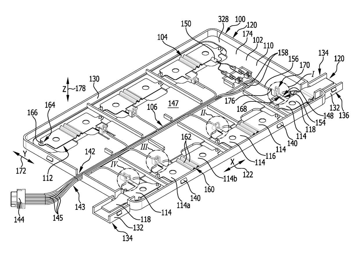
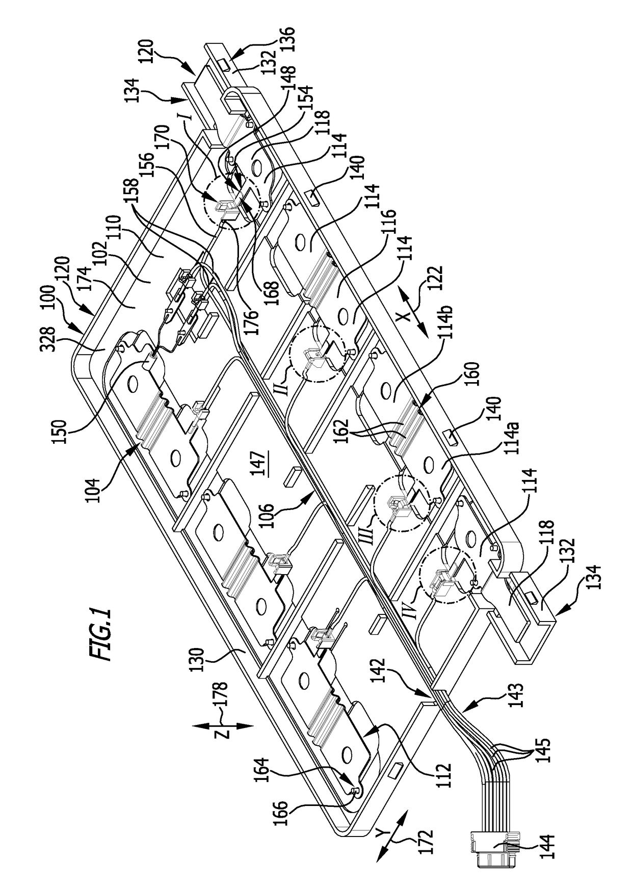
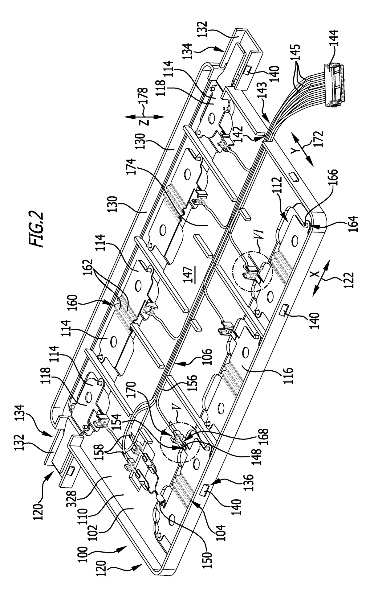
[0262]a signal-line-system-side positioning element 168 and an associated carrier-element-side positioning element 170 which is illustrated in FIGS. 17 to 19, differs from the previously described embodiments in that the end section 220 of the signal line 145 is not connected in electrically conductive manner to the signal-line-system-side positioning element 16 in a terminal region 176 that is spaced from the respectively associated cell connector 116 or current termination 118 in the assembled state of the cell contacting system 100, but rather, it is connected thereto in the contact region 182 of the signal-line-system-side positioning element 168.

[0263]For this purpose, the contact region 182 of the signal-line-system-side positioning element 168 in this embodiment comprises crimping elements 222 by means of which the (preferably stripped) end section 220 of the signal line 145 is fixable to the contact region 182 by a crimping process.

[0264]In this embodiment, the contact regio...


PUM


Abstract

A cell contacting system for an electro-chemical device includes a plurality of electro-chemical cells and a current line system, wherein the cell contacting system includes a signal line system having signal lines for connecting a respective signal source to a signal line termination or to a monitoring device of the cell contacting system and a carrier element which carries the signal line system. The cell contacting system further includes at least one signal-line-system-side positioning element which is fixed to a signal line of the signal line system and at least one carrier-element-side positioning element which is fixed at least temporarily to the carrier element, wherein the signal-line-system-side positioning element is connected to the carrier-element-side positioning element at least temporarily in such a way that the signal-line-system-side positioning element is positioned in a desired position relative to a cell connector or a current termination of the current line system.

Description

RELATED APPLICATIONS[0001]This application is a continuation application of PCT / EP2015 / 066044, filed on Jul. 14, 2015, which claims priority to German Pat. App. No. 10 2014 110 211.8, filed on Jul. 21, 2014, both of which are incorporated herein by reference in their entireties.FIELD OF DISCLOSURE[0002]The present invention relates to a cell contacting system for an electro-chemical device which comprises a plurality of electro-chemical cells and a current line system, wherein the cell contacting system comprises a signal line system having a plurality of signal lines for connecting a respective signal source to a signal line termination or to a monitoring device of the cell contacting system in electrically conductive manner and a carrier element which carries the signal line system.BACKGROUND[0003]Such a cell contacting system serves the purpose of enabling an individual cell to be monitored in regard to physical measured variables such as the voltage and the temperature for examp...

Claims


Application Information

Patent Timeline
IPC IPC(8): H01M2/20H01M10/42H01M2/10H01M10/48C25B9/04H01R25/16H01M50/209H01M50/298H01M50/514
CPCH01M2/206C25B9/04H01R25/162H01M2010/4278H01M10/482H01M10/425H01M2/1077H01M10/486H01R9/16H01M50/209H01M50/298H01M50/514Y02E60/10C25B9/65
Inventor ROEMER, RUBENHOENLE, UDOKAZMAIER, STEFANFRITZ, WOLFGANG
Owner ELRINGKLINGER AG
Why Eureka
Try Eureka