Supporting body comprising a receiving groove for a reinforcement panel

a technology of receiving groove and reinforcement panel, which is applied in the direction of belt/chain/gearing, mechanical equipment, etc., can solve the problems of increasing the manufacturing complexity of this approach, affecting the mechanical stability of the supporting body, so as to improve the mechanical load capacity, improve the mechanical stability, and simplify the manufacturing process

Active Publication Date: 2017-05-18
SCHAEFFLER TECH AG & CO KG
View PDF3 Cites 0 Cited by
  • Summary
  • Abstract
  • Description
  • Claims
  • Application Information

AI Technical Summary

Benefits of technology

[0009]The supporting body is advantageously manufactured as a single piece by injection molding, which simplifies the manufacturing process.
[0010]According to one advantageous refinement of the present invention, multiple delimiting elements are provided on both sides of the elongated receiving groove, which thus define the receiving groove in the manner of laterally arranged crenellations. The advantage of this approach is that the dimensions and positions of the delimiting elements may be variably configured to increase, for example, the mechanical load capacity.
[0011]According to one advantageous refinement of the present invention, each gap between two delimiting elements on one side of the receiving groove is situated opposite a delimiting element on the other side. This results in a gap-free projection in a lateral projection of the delimiting elements on both sides, which increases the mechanical load capacity.
[0012]In another improvement of this specific embodiment, each delimiting element on one side, except for the first and the last delimiting elements viewed in the longitudinal direction, is situated opposite a gap on the other side, which has the same dimensions as this delimiting element. As in the last specific embodiment, this results in a continuously gap-free projection, in which the delimiting elements are additionally alternatingly arranged, in which no overlaps furthermore occur in the projection. Additional material is saved thereby while maintaining the same mechanical stability.
[0013]According to one measure which improves the present invention, one or multiple, preferably all, delimiting elements are bent or tilted in the direction of the receiving groove, so that, in the vicinity of the rear side of the supporting body, they are situated a greater distance from each other than from the supporting body. This results in a width tolerance of the reinforcement panel or the receiving groove.

Problems solved by technology

Great forces, which may bend or otherwise structurally damage tensioning or guide rails manufactured from plastic, for example by injection molding, thus occasionally occur, particularly in tensioning rails but also in guide rails.
This receiving groove should neither be too large, since the reinforcement panel may thus, for example, vibrate or fall out of the receiving groove, nor be too narrowly dimensioned, since the insertion of the reinforcement panel is then made more difficult or impossible.
The disadvantage thereof is, in particular, the increased manufacturing complexity of this approach.

Method used


Image

  • Supporting body comprising a receiving groove for a reinforcement panel
  • Supporting body comprising a receiving groove for a reinforcement panel

Examples


Embodiment Construction

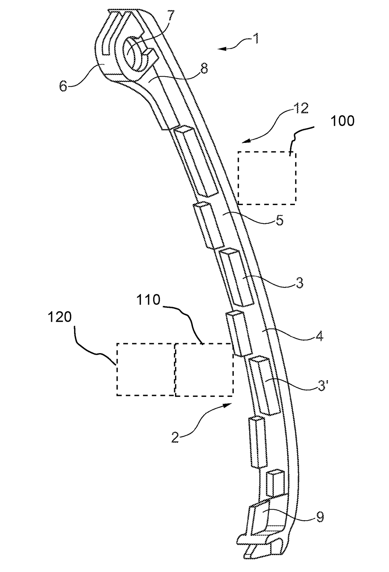
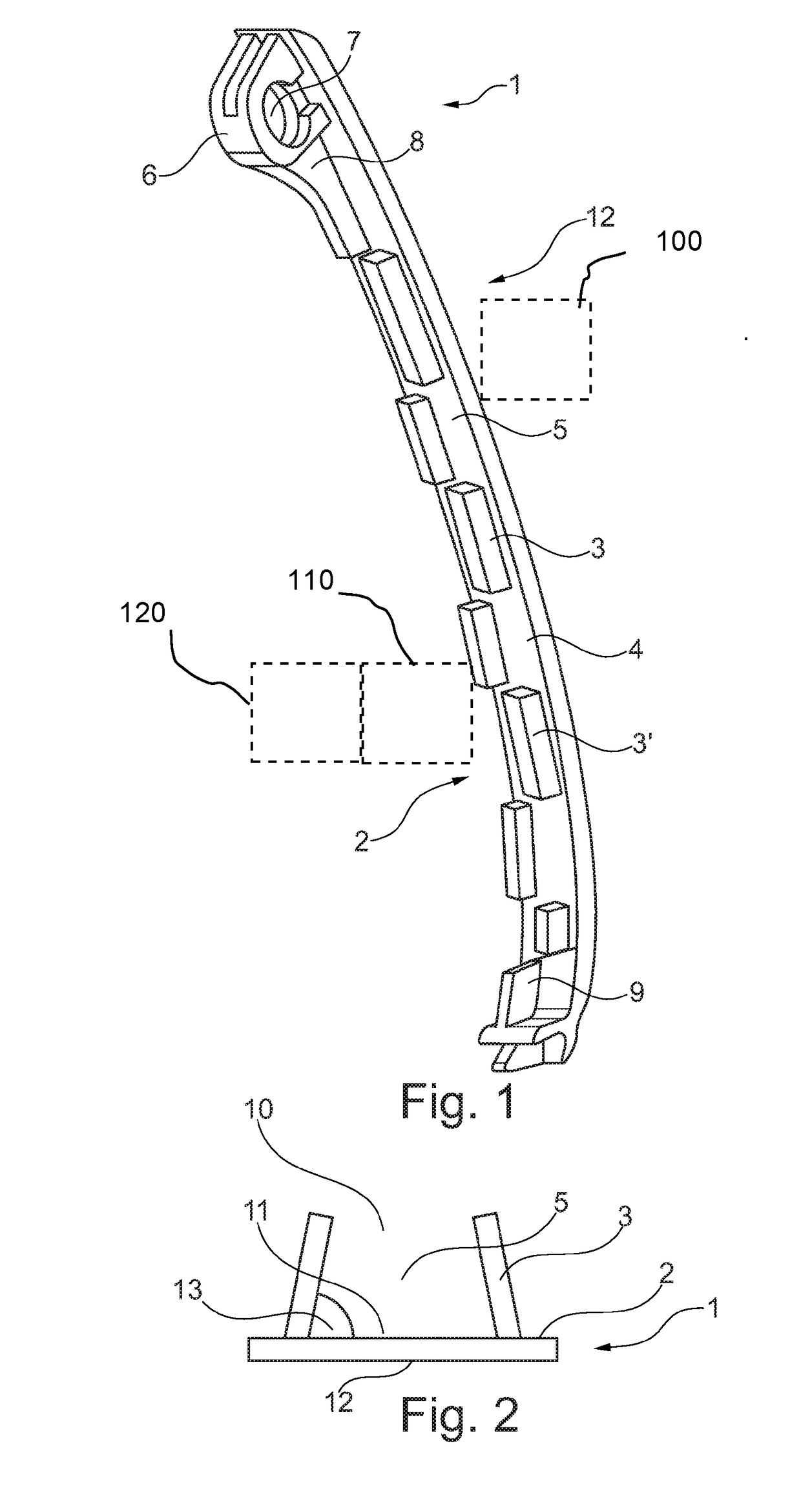
[0017]According to FIG. 1, an elongated supporting body 1 has a rear side 2, on which delimiting elements 3 are alternatingly arranged. In this case, alternating means that one gap 4 is situated longitudinally between each of two delimiting elements 3, the one delimiting element 3 on the other side being opposite elongated receiving groove 5 formed by delimiting elements 3. A receiving element 6, which has a circular recess 7 for accommodating a bolt of a traction mechanism drive 100, illustrated schematically, for the purpose of the swiveling support of the supporting body, is also arranged on rear side 2. Along the longitudinal direction of supporting body 1, delimiting elements 3 form receiving groove 5 for accommodating a reinforcement panel 110 illustrated schematically and pressured by a pressure means 120, also schematically illustrated. Delimiting elements 3 are arranged in such a way that one delimiting element 3, except for first delimiting element 8 and last delimiting el...


PUM


Abstract

A supporting body (1) for guiding or tensioning a circumferential traction mechanism of a traction drive, a front side (12) that has an elongated sliding surface for making contact with the traction mechanism, a rear side (2) that lies opposite and includes an elongated receiving groove (5) for form-fittingly receiving a reinforcement panel, the receiving groove (5) being formed by delimiting elements (3) which protrude, at the sides of the groove, from the rear side, and at least two delimiting elements (3, 3′) on one side of the receiving groove (5) being separated in the longitudinal direction by a spacing in the form of a gap (4).

Description

[0001]The present invention relates to a supporting body for guiding or tensioning a circumferential traction mechanism of a traction mechanism drive, including a front side which has a longitudinal sliding surface for contact with the traction mechanism, a diametrically opposed rear side which has an elongated receiving groove for the form-fitting accommodation of a reinforcement panel, the receiving groove being formed by delimiting elements which protrude, at sides of the groove, from the rear side.[0002]The field of use of the present invention extends to traction mechanism drives in which torque or kinetic energy is to be transmitted from a first shaft to a second shaft with the aid of a circumferential traction mechanism. To limit the degrees of freedom of the movement of the circumferential traction mechanism, guide rails and tensioning rails are used in the known prior art, guide rails being fixedly connected all over to the bearing of the shafts, and tensioning rails being ...

Claims


Application Information

Patent Timeline
Patent Type & Authority Applications(United States)
IPC IPC(8): F16H7/08F16H7/18
CPCF16H7/08F16H2007/185F16H2007/0872F16H7/18
Inventor LANG, JOHANNESKROHMER, JOERG-DIETRICH
Owner SCHAEFFLER TECH AG & CO KG
Why Eureka
Try Eureka