Chain tensioner
a chain tensioner and tensioner technology, applied in the direction of valves, functional valve types, machines/engines, etc., can solve the problems of increased noise, poor engine fuel economy, increased weight and cost, etc., and achieves higher valve opening pressure, higher speed, and higher load applications.
- Summary
- Abstract
- Description
- Claims
- Application Information
AI Technical Summary
Benefits of technology
Problems solved by technology
Method used
Image
Examples
embodiment 1
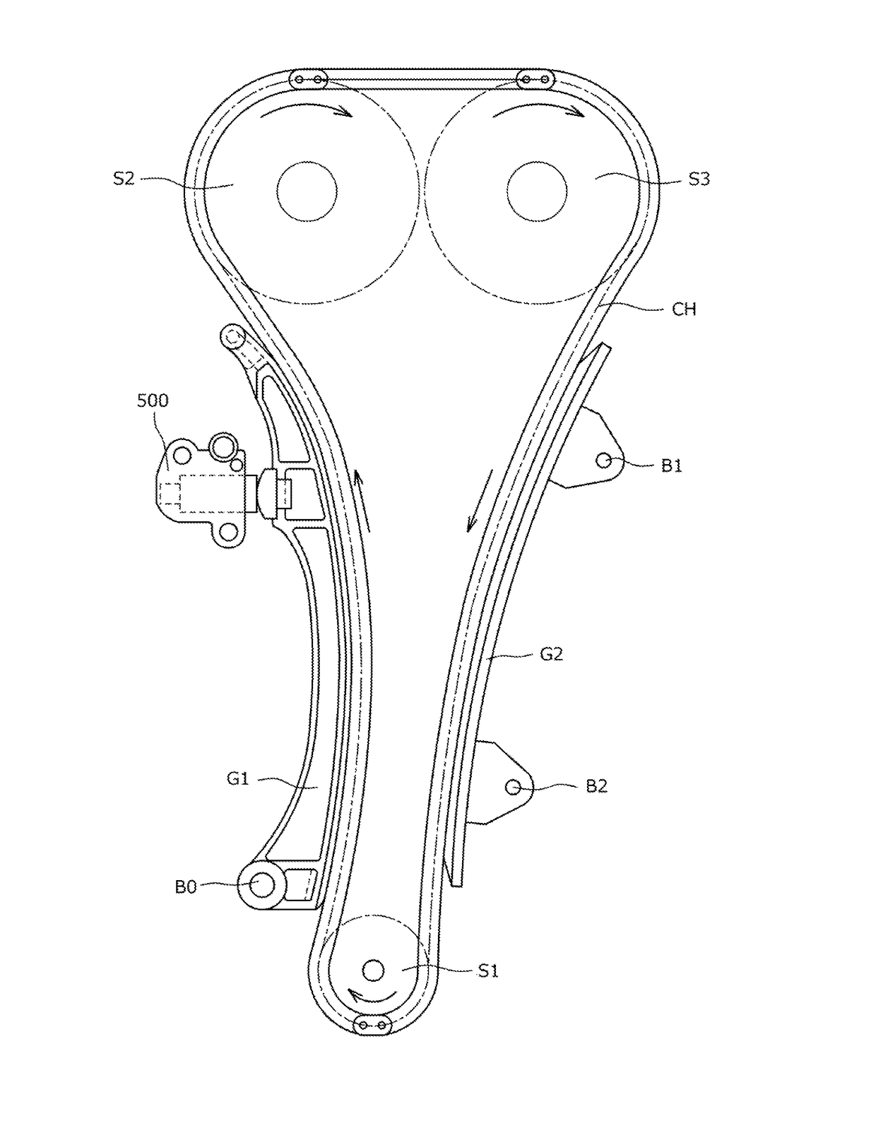
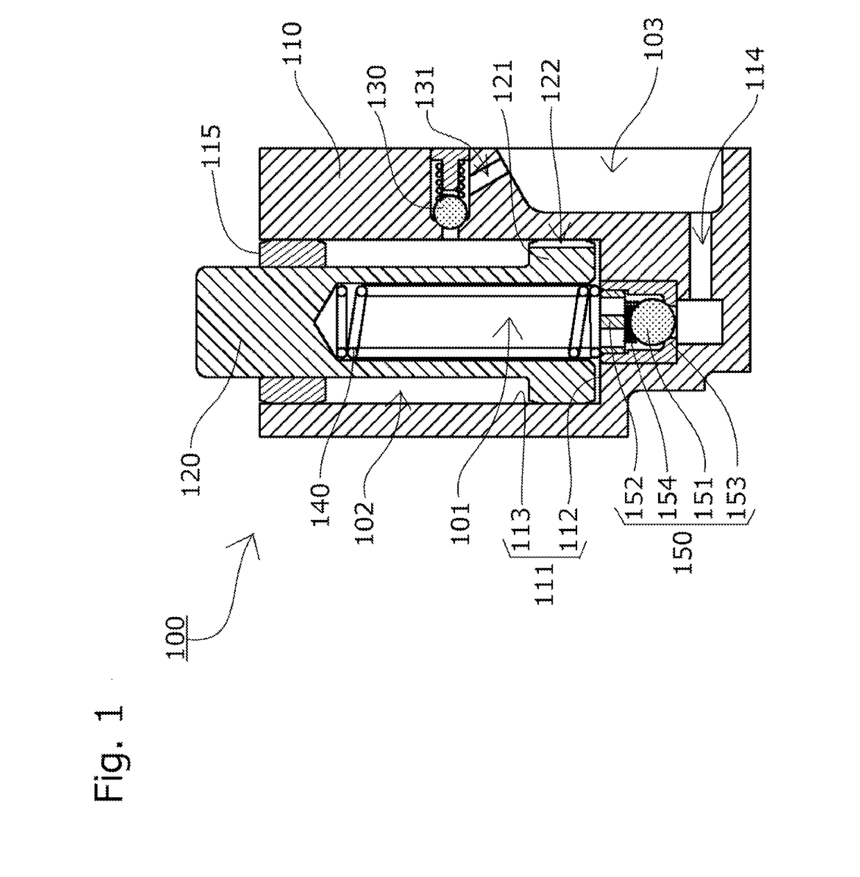
[0035]A chain tensioner 100 according to a first embodiment of the present invention will be described with reference to the drawings.
[0036]The chain tensioner 100 includes, as shown in FIG. 1, a tensioner body 110 having a cylindrical plunger bore 111 with one open end, a cylindrical plunger 120 slidably inserted in the plunger bore 111, and a coil spring 140 that is biasing means accommodated inside an oil pressure chamber 101 formed between the plunger bore 111 and the plunger 120 such as to be able to expand and contract and to urge the plunger 120 in an advancing direction.
[0037]An oil supply part 103, to which oil is supplied from the engine or the like, is formed in the surface of the tensioner body 110 that is attached to the engine or the like.
[0038]In a bottom part 112 of the plunger bore 111 is provided a check valve unit 150, so that the oil supplied to the oil supply part 103 is delivered through an oil supply hole 114 via the check valve unit 150 into the oil pressure ...
embodiment 2
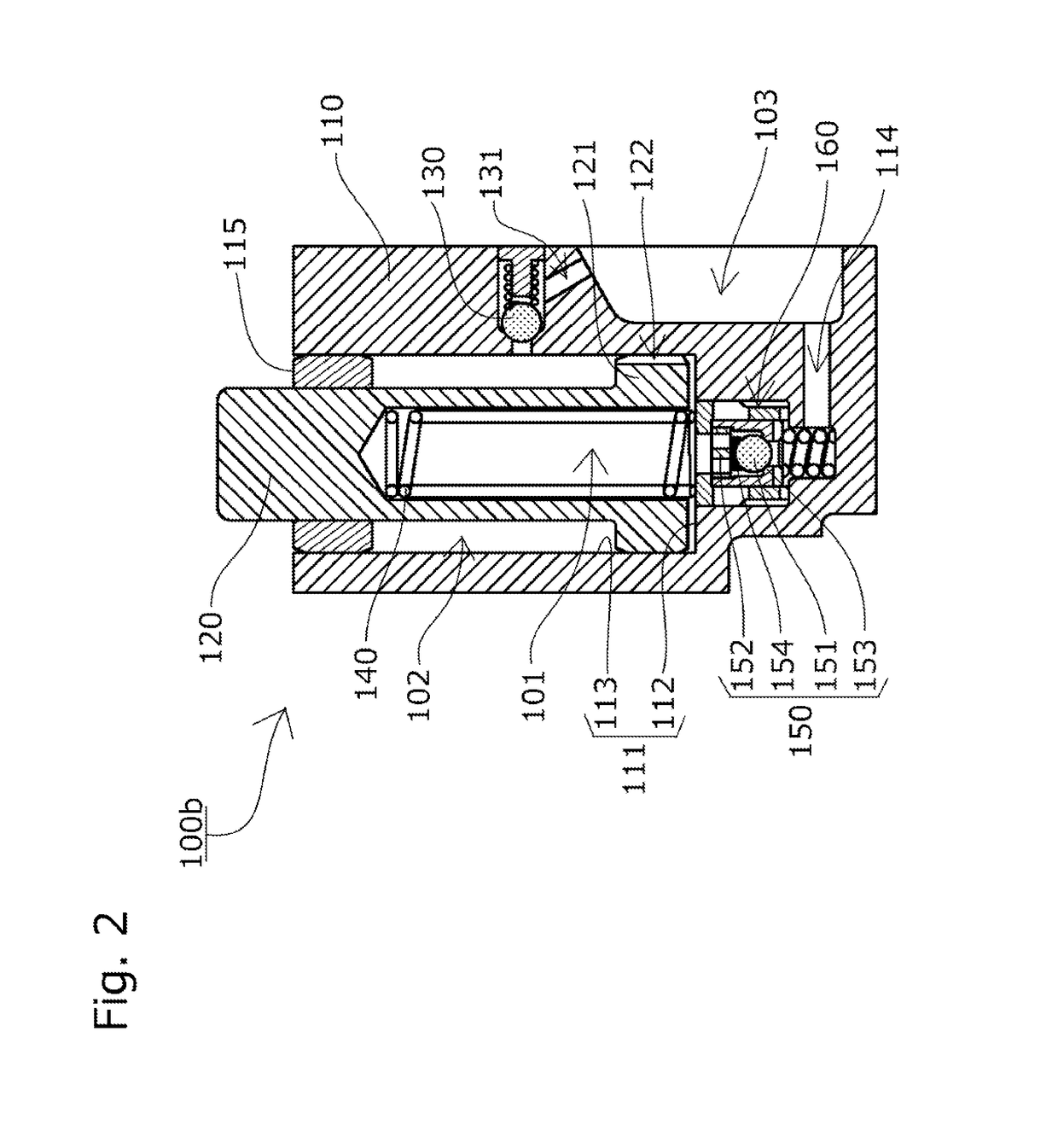
[0057]The chain tensioner 100b according to the second embodiment of the present invention includes, as shown in FIG. 2, a second relief valve unit 160 that allows the oil to circulate back to the oil supply part 103 when the pressure of the oil pressure chamber 101 reaches or exceeds a predetermined high level. The check valve unit 150 is disposed as a valve element of the second relief valve unit 160, and the second relief valve unit 160 and the check valve unit 150 are formed integral with each other.
[0058]The second relief valve unit 160 includes, as shown in FIG. 3A, a relief sleeve 161 that slidably holds the check valve unit 150 inside, a relief valve seat 162 that opens and closes as the check valve unit 150 slides, and a unit pressing spring 163 for pressing the check valve unit 150 toward the relief valve seat 162. One end of the unit pressing spring 163 is seated inside the tensioner body 110.
[0059]Optionally, a spring retainer that supports and fixes the unit pressing sp...
PUM
 Abstract
Description
Claims
Application Information
 - R&D
- Intellectual Property
- Life Sciences
- Materials
- Tech Scout
- Unparalleled Data Quality
- Higher Quality Content
- 60% Fewer Hallucinations
Browse by: Latest US Patents, China's latest patents, Technical Efficacy Thesaurus, Application Domain, Technology Topic, Popular Technical Reports.
© 2025 PatSnap. All rights reserved.Legal|Privacy policy|Modern Slavery Act Transparency Statement|Sitemap|About US| Contact US: help@patsnap.com


