Chain tensioner

a chain tensioner and tensioner technology, applied in the direction of valves, functional valve types, machines/engines, etc., can solve the problems of increased noise, poor engine fuel economy, increased weight and cost, etc., and achieves higher valve opening pressure, higher speed, and higher load applications.

Active Publication Date: 2019-03-05
TSUBAKIMOTO CHAIN CO
View PDF11 Cites 1 Cited by
  • Summary
  • Abstract
  • Description
  • Claims
  • Application Information

AI Technical Summary

Benefits of technology

[0012]In such a chain tensioner, because of the worry that rattling may occur due to looseness in the chain during high-speed, high-load operation, or at the start of the engine when the hydraulic damping force does not effectively act due to entrapped air or the like, it is desirable that the biasing means be designed to have a large spring load, or the plunger be made with a large diameter. However, the biasing means with a large spring load would press the chain more than necessary during normal range operation, and the increased chain tension would deteriorate friction properties between the chain and its running surface, and would further lead to an increased noise and poorer engine fuel economy.

Problems solved by technology

However, the biasing means with a large spring load would press the chain more than necessary during normal range operation, and the increased chain tension would deteriorate friction properties between the chain and its running surface, and would further lead to an increased noise and poorer engine fuel economy.
On the other hand, increasing the plunger diameter would require a larger design for the chain tensioner itself, and bring up problems such as larger installation space being required, and increased weight and cost.
However, with the technique described in Japanese Patent Application Laid-open No. 2000-240744, the hydraulic damping effect does not act immediately after the start of the engine, and when the biasing means has a small spring load, the preventive effects were limited.

Method used


Image

  • Chain tensioner
  • Chain tensioner
  • Chain tensioner

Examples


embodiment 1

[0035]A chain tensioner 100 according to a first embodiment of the present invention will be described with reference to the drawings.

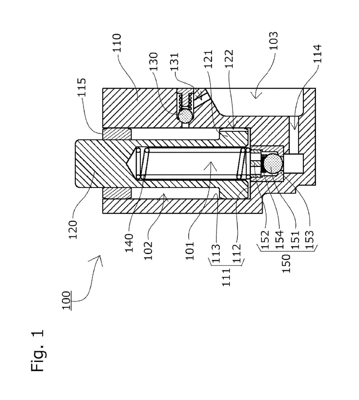
[0036]The chain tensioner 100 includes, as shown in FIG. 1, a tensioner body 110 having a cylindrical plunger bore 111 with one open end, a cylindrical plunger 120 slidably inserted in the plunger bore 111, and a coil spring 140 that is biasing means accommodated inside an oil pressure chamber 101 formed between the plunger bore 111 and the plunger 120 such as to be able to expand and contract and to urge the plunger 120 in an advancing direction.

[0037]An oil supply part 103, to which oil is supplied from the engine or the like, is formed in the surface of the tensioner body 110 that is attached to the engine or the like.

[0038]In a bottom part 112 of the plunger bore 111 is provided a check valve unit 150, so that the oil supplied to the oil supply part 103 is delivered through an oil supply hole 114 via the check valve unit 150 into the oil pressure ...

embodiment 2

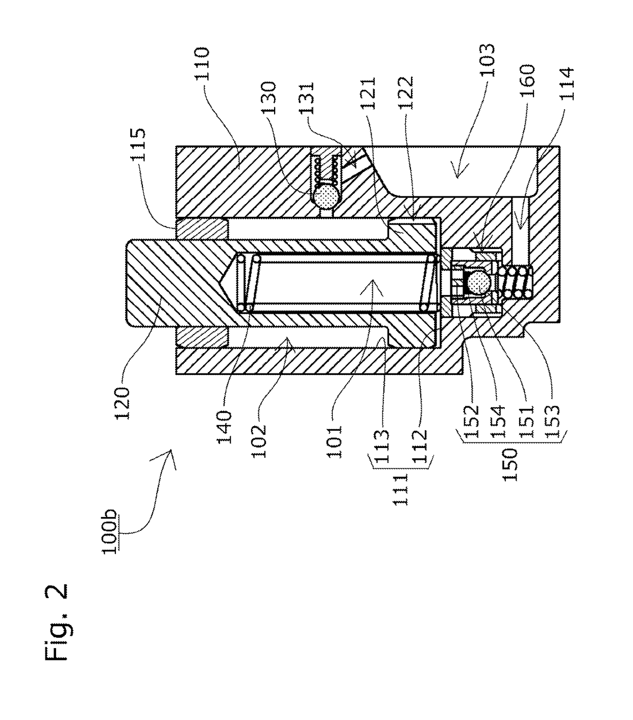
[0057]The chain tensioner 100b according to the second embodiment of the present invention includes, as shown in FIG. 2, a second relief valve unit 160 that allows the oil to circulate back to the oil supply part 103 when the pressure of the oil pressure chamber 101 reaches or exceeds a predetermined high level. The check valve unit 150 is disposed as a valve element of the second relief valve unit 160, and the second relief valve unit 160 and the check valve unit 150 are formed integral with each other.

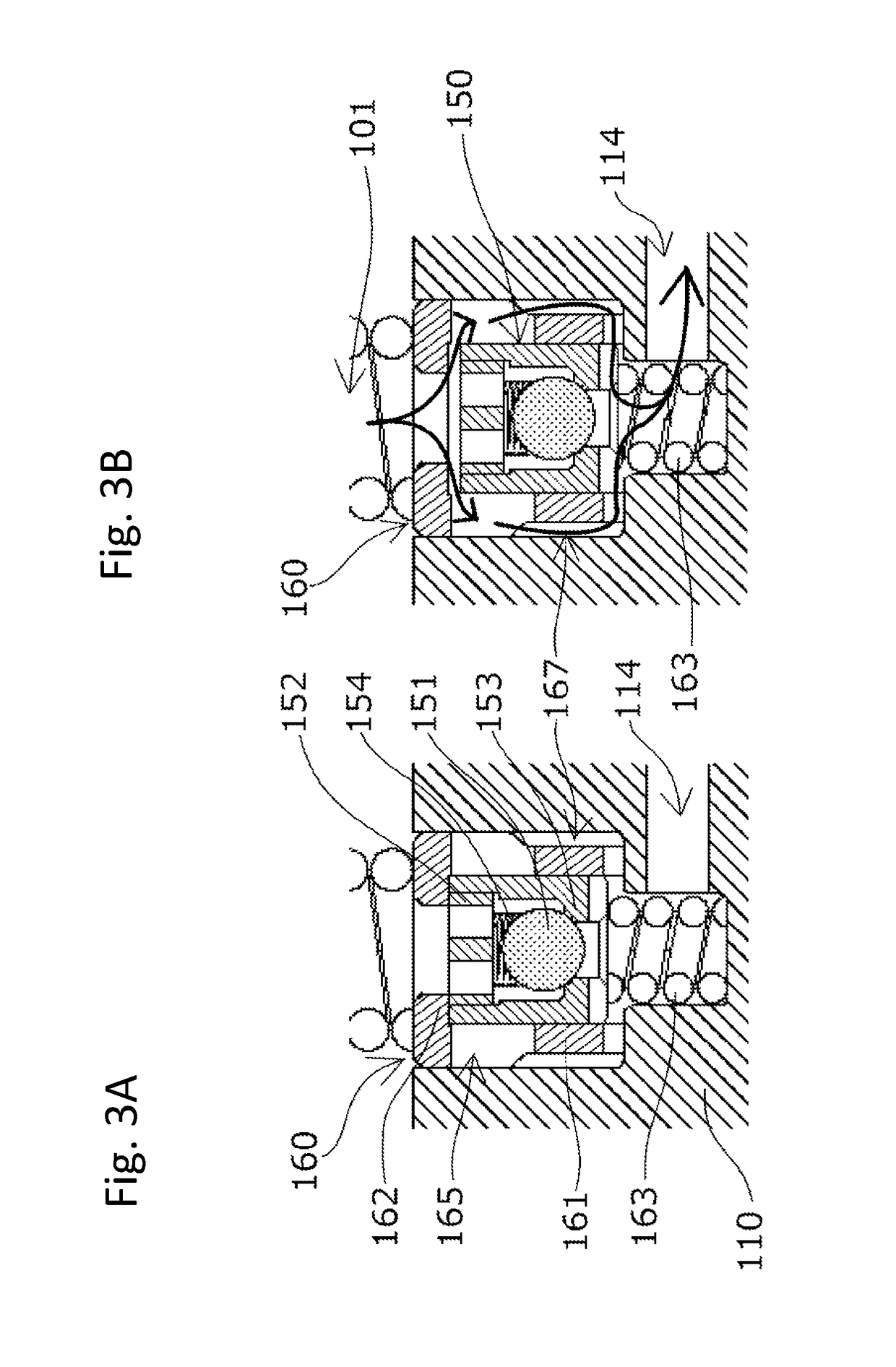
[0058]The second relief valve unit 160 includes, as shown in FIG. 3A, a relief sleeve 161 that slidably holds the check valve unit 150 inside, a relief valve seat 162 that opens and closes as the check valve unit 150 slides, and a unit pressing spring 163 for pressing the check valve unit 150 toward the relief valve seat 162. One end of the unit pressing spring 163 is seated inside the tensioner body 110.

[0059]Optionally, a spring retainer that supports and fixes the unit pressing sp...


PUM


Abstract

To provide a chain tensioner capable of constantly applying an appropriate pressing force under any situations including high-speed, high-load operation, at the start of an engine, and normal range operation, without an increase in size or amount of oil consumption. A check valve unit 150 is disposed between an oil pressure chamber 101 and an oil supply part 103. A second oil pressure chamber 102 is formed between an outer circumferential surface of a plunger 120 and a cylindrical surface 113 of a plunger bore 111, into which oil leaking from the oil pressure chamber 101 flows and whose volume increases as the plunger 120 retracts. Further provided is a relief valve unit 130 that releases oil when the pressure of the second oil pressure chamber 102 reaches or exceeds a predetermined high level.

Description

BACKGROUND OF THE INVENTION[0001]1. Field of the Invention[0002]The present invention relates to a chain tensioner that includes a tensioner body having a cylindrical plunger bore with one open end, a cylindrical plunger slidably inserted in the plunger bore, and biasing means accommodated inside an oil pressure chamber formed between the plunger bore and the plunger such as to freely expand and contract and to urge the plunger in an advancing direction, and that maintains appropriate tension of a chain.[0003]2. Description of the Related Art[0004]It has been common practice to use a chain tensioner for maintaining appropriate tension of a chain. For example, a chain guide mechanism has been known, which slidably guides, by means of a guide shoe, a transmission chain such as an endless roller chain passing over respective sprockets of a crankshaft and a cam shaft inside an engine room, and which uses a chain tensioner to press a pivoting chain guide having the guide shoe to maintain...

Claims


Application Information

Patent Timeline
Patent Type & Authority Patents(United States)
IPC IPC(8): F16H7/08
CPCF16H7/0848F16H2007/0806F16H2007/0893F16H2007/0859F16H2007/0872F16H2007/0814F16H7/08F02B67/06F16K15/044F16K17/04
Inventor KUREMATSU, YUJI
Owner TSUBAKIMOTO CHAIN CO
Why Eureka
Try Eureka