Ranging device with imaging capability

Active Publication Date: 2017-05-18
STMICROELECTRONICS (GRENOBLE 2) SAS
View PDF0 Cites 62 Cited by
  • Summary
  • Abstract
  • Description
  • Claims
  • Application Information

AI Technical Summary

Benefits of technology

[0010]It is an aim of embodiments of the present description to

Problems solved by technology

A difficulty is that, depending on the 2-dimensional scene content, some of the SPADs in the array may provide an

Method used


Image

  • Ranging device with imaging capability
  • Ranging device with imaging capability
  • Ranging device with imaging capability

Examples


Embodiment Construction

[0036]Throughout the present description, the term “connected” is used to designate a direct electrical connection between two elements, whereas the term “coupled” is used to designate an electrical connection between two elements that may be direct, or may be via one or more other components such as resistors, capacitors or transistors. Furthermore, as used herein, the term “around” is used to designate a range of + / −10 percent of the value in question.

[0037]While in the present description embodiments are described comprising a ranging device in the form of a SPAD array, the principles of the circuit and method described herein for calculating a distance to an object could be applied to arrays formed of other types of photon detection devices.

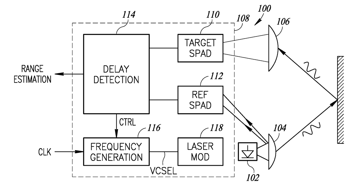
[0038]FIG. 1 schematically illustrates a ranging device 100 implementing a ranging function. The device 100 comprises a light source 102, which is for example a laser, for generating an optical signal, formed for example of a beam of optical ...


PUM


Abstract

A ranging device includes an array of photon detection devices adapted to receive an optical signal reflected by an object in an image scene. First and second logic devices are adapted to respectively combine the outputs of first and second pluralities of the photon detection devices. A first range detection circuit is coupled to outputs of the first and second logic devices and a first counter is coupled to the output of the first logic device and adapted to generate a first pixel value by counting events generated by the first plurality of photon detection devices. A second counter is coupled to the output of the second logic device and is adapted to generate a second pixel value by counting events generated by the second plurality of photon detection devices. The first and second pixel values may be used in estimating a range to the object in the image scene.

Description

[0001]This application claims the priority benefit of French Patent application number 15 / 60949, filed on Nov. 16, 2015, the contents of which is hereby incorporated by reference in its entirety to the maximum extent allowable by law.BACKGROUND[0002]1. Technical Field[0003]The present disclosure relates to the field of ranging based on a time of flight calculation, and in particular to a ranging device with imaging capabilities.[0004]2. Description of the Related Art[0005]SPAD (single-photon avalanche diode) arrays can be used for a variety of applications, including for ranging, for 2D or 3D gesture recognition and for 3D imaging. A device for such applications generally comprises a light source for transmitting an optical pulse into the image scene. The light reflected back from any object in the image scene is detected by the SPAD array, and used to determine the time of flight of the optical pulse. The distance from the object to the device can then be deduced based on this time...

Claims


Application Information

Patent Timeline
IPC IPC(8): G01S7/486G01S17/10H01L27/144G01S7/4863G01S7/4865G01S7/4914G01S7/4915
CPCG01S7/4863G01S17/10H01L27/1446G01S17/36G01S7/4865G01S7/487G01S7/4914G01S7/4915G01S7/493
Inventor DRADER, MARCMELLOT, PASCAL
Owner STMICROELECTRONICS (GRENOBLE 2) SAS
Why Eureka
Try Eureka