Model setting method, forming simulation method, production method of forming tool, program, computer-readable recording medium having program recorded thereon, and finite element model

Inactive Publication Date: 2017-05-18
NIPPON STEEL CORP
View PDF0 Cites 6 Cited by
  • Summary
  • Abstract
  • Description
  • Claims
  • Application Information

AI Technical Summary

Benefits of technology

The invention can accurately and efficiently simulate the forming of metal plates.

Problems solved by technology

In these components, forming defects such as cracks and wrinkles, dimensional accuracy failure associated with springback, and the like can occur during a forming process, in some cases.
Hence, there is a problem in that consistency between an analysis result of the forming simulation and an actual measured value of the real formed piece becomes low in the above analysis model.
In particular, high strength material is used actively to reduce weights of components and to improve a collision function, and a forming load increases when forming a high strength metal plate, and thus influence by the elastic deformation of the forming tool in the forming simulation is unable to be disregarded.
However, when the forming tool is modeled as the solid element, significant labor and time are necessary in each of creation of the analysis model (mesh division) and analysis execution, as compared with a case of modeling the forming tool as a shell element.
Hence, using this analysis model is not realistic at a mass production site that works on development of many components.

Method used


Image

  • Model setting method, forming simulation method, production method of forming tool, program, computer-readable recording medium having program recorded thereon, and finite element model
  • Model setting method, forming simulation method, production method of forming tool, program, computer-readable recording medium having program recorded thereon, and finite element model
  • Model setting method, forming simulation method, production method of forming tool, program, computer-readable recording medium having program recorded thereon, and finite element model

Examples


working example 1

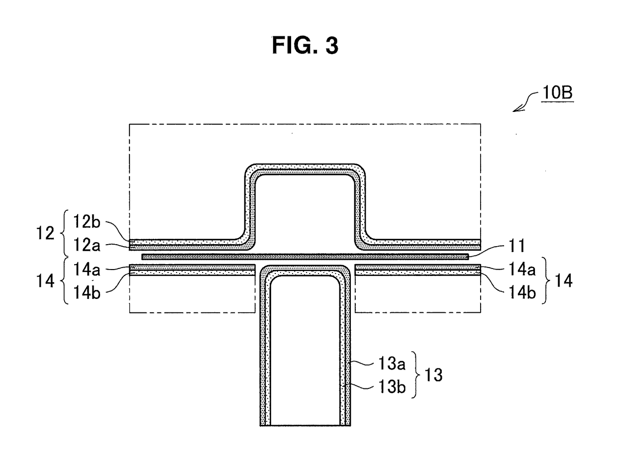
[0106]As working example 1, the finite element model of the press forming die is created by setting the surface layer as the elastic body shell element, and the base body as the rigid body shell element. The finite element model of the working example 1 is illustrated in FIG. 13. In the working example 1, the finite element model of the press forming die is built by setting the surface layer 12a of the die model 12, the surface layer 13a of the punch model 13, and the surface layer 14a of the blank holder model 14 as the shell elements of the elastic bodies, and the base body 12b of the die model 12, the base body 13b of the punch model 13, and the base body 14b of the blank holder model 14 as the shell elements of the rigid bodies, and the metal plate model 11 as the shell element of the elasto-plastic body, as illustrated in FIG. 13. In this finite element model, the thicknesses of the surface layers are set to 2 mm, and the shell elements are located at the centers of the thickne...

working example 2

[0107]As working example 2, the finite element model of the press forming die is created by setting the surface layer as the elastic body thick-walled shell element, and the base body as the rigid body shell element. The finite element model of the working example 2 is illustrated in FIG. 14. In the working example 2, the finite element model of the press forming die is built by setting the surface layer 12a of the die model 12, the surface layer 13a of the punch model 13, and the surface layer 14a of the blank holder model 14 as the thick-walled shell elements of the elastic bodies, and the base body 12b of the die model 12, the base body 13b of the punch model 13, and the base body 14b of the blank holder model 14 as the shell elements of the rigid bodies, and the metal plate model 11 as the shell element of the elasto-plastic body, as illustrated in FIG. 14. Note that, in FIG. 14, the base body 14b of the blank holder model 14 is hidden by the surface layer 14a and is not depicte...

working example 3

[0108]As the working example 3, the finite element model of the press forming die is created by setting the surface layer as the elastic body solid element divided once in the thickness direction, and the base body as the rigid body shell element. The finite element model of the working example 3 is the same on display as the finite element model of the die of the working example 2 illustrated in FIG. 14. In the working example 3, the finite element model of the press forming die is built by setting the surface layer 12a of the die model 12, the surface layer 13a of the punch model 13, and the surface layer 14a of the blank holder model 14 as the solid elements of the elastic bodies, and the base body 12b of the die model 12, the base body 13b of the punch model 13, and the base body 14b of the blank holder model 14 as the shell elements of the rigid bodies, and the metal plate model 11 as the shell element of the elasto-plastic body. In this finite element model, the thickness of t...


PUM

PropertyMeasurementUnit
Thicknessaaaaaaaaaa
Thicknessaaaaaaaaaa
Plasticityaaaaaaaaaa

Abstract

[Object] To provide a model setting method of a finite element model used for forming simulation, which is capable of executing forming simulation of a metal plate highly accurately and efficiently.[Solution] Provided is a model setting method for setting a finite element model for simulating forming of a metal plate by a forming tool by using a finite element method, by a processor included in a computer, the model setting method including: in setting a forming tool model that represents the forming tool, setting at least a part of a metal plate contacting surface that contacts the metal plate, in the forming tool model, as a surface layer that has characteristics of an elastic body or an elasto-plastic body; and setting a part that supports the surface layer in the forming tool model, as a base body that has characteristics of a rigid body.

Description

TECHNICAL FIELD[0001]The present invention relates to a model setting method of a finite element model that is used in forming simulation of a metal plate by a finite element method, a forming simulation method that uses a set finite element model, a production method of a forming tool that uses the forming simulation method, a program, a computer-readable recording medium having a program recorded thereon, and a finite element model.BACKGROUND ART[0002]Components that are formed by press forming, roll forming, and the like of a metal plate by means of a forming tool are heavily used in automotive components and home appliances. In these components, forming defects such as cracks and wrinkles, dimensional accuracy failure associated with springback, and the like can occur during a forming process, in some cases. In order to study a method to prevent the above, forming simulation by a finite element method is actively used in recent years.[0003]In general, the forming simulation of a...

Claims


Application Information

Patent Timeline
IPC IPC(8): G06F17/50
CPCG06F17/5018B21D37/20G06F2217/12G06F2217/42B21D53/88B21D22/00G06F2113/24G06F2119/18G06F30/23Y02P90/02G06F30/00
Inventor SUZUKI, TOSHIYANAKAZAWA, YOSHIAKI
Owner NIPPON STEEL CORP
Why Eureka
Try Eureka