A Parallel Calculation Method of Dynamic Mesh in Lubrication Flow Area of ​​Rotor-sliding Bearing System

A sliding bearing and parallel computing technology, which is applied in the field of computational fluid dynamics simulation, can solve the problems of non-existence, data export errors, and inability to obtain accurate shaft journal center coordinates, so as to ensure calculation accuracy, overcome low simulation efficiency, and improve The effect of computational efficiency

Active Publication Date: 2022-05-20
CHINA UNIV OF PETROLEUM (EAST CHINA)
View PDF6 Cites 0 Cited by
  • Summary
  • Abstract
  • Description
  • Claims
  • Application Information

AI Technical Summary

Problems solved by technology

[0005] In the process of realizing the present invention, the inventors found that there are at least the following problems in the prior art: 1. In the calculation process of sliding bearing lubrication flow domain based on the user-defined variable flow field dynamic mesh technology, only single-core calculation can be performed, Restricts the calculation speed of the flow field; 2. During the parallel calculation process, the update calculation of the grid nodes in the flow field cannot be performed within the same time step; 3. During the parallel calculation process, the coordinates of the center of the journal cannot be accurately obtained and cannot be used Time-domain and frequency-domain variation of shaft center trajectory for fast stability analysis of rotor-sliding bearing system
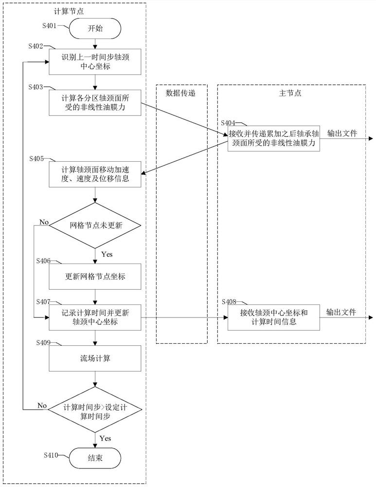
[0007] 1. The original user-defined moving grid program will control the movement of nodes to update the grid node coordinates in the moving grid area every time a time step passes, and the displacement of the grid node coordinates in each time step depends on The magnitude of the nonlinear oil film force at the journal in the journal bearing flow domain. In the process of applying the original user-defined dynamic mesh program to parallel calculations, the mesh including the journal surface is divided into multiple regions and mapped separately To perform calculations on multiple computing nodes, because the original program lacks the function macro PRF_GRSUM to realize global data summation, and the function macro NODE_TO_HOST_REAL_N to realize the transfer of information from computing nodes to the master node, if the original user-defined dynamic grid is still used The program, each calculation node calculates separately, cannot control the exchange of information between each node, and cannot communicate and summarize the oil film pressure information at the journal in the sliding bearing flow domain, resulting in the inability to summarize the nonlinear oil film pressure information at the journal, which directly leads to grid nodes. The displacement of the movement cannot be calculated, so the original user-defined moving mesh program can only perform single-core calculations
[0008] 2. Since the original user-defined dynamic grid program does not have the function of information transmission and information aggregation under parallel conditions in the process of applying parallel computing, the updated flow field information cannot be aggregated to a computing node in time (calculation number 0 node) for calculation, the nonlinear oil film force at the journal in the entire flow field area cannot be obtained. At the same time, the accurate acquisition of the nonlinear oil film force at the journal is the basis for obtaining the coordinate position of the grid node. If the nonlinear oil film force cannot be obtained, the Unable to update grid node coordinates in the same time step
At this time, since each grid region executes the same user-defined dynamic grid program without distinction between the master node and the computing node during the parallel computing process, the master node cannot recognize the correct program command, resulting in data export errors

Method used


Image

  • A Parallel Calculation Method of Dynamic Mesh in Lubrication Flow Area of ​​Rotor-sliding Bearing System
  • A Parallel Calculation Method of Dynamic Mesh in Lubrication Flow Area of ​​Rotor-sliding Bearing System
  • A Parallel Calculation Method of Dynamic Mesh in Lubrication Flow Area of ​​Rotor-sliding Bearing System

Examples


Embodiment 1

[0106] Embodiment 1: Parallel calculation of a sliding bearing with two oil wedge oil inlet ports arranged at both ends along the radial direction.

[0107] 1.1 Establish the research object as the gap lubrication area and the lubrication path flow channel of the fixed pad cylindrical sliding bearing system with two oil inlets equipped with two oil wedges along the radial direction, which is defined as the lubrication flow area, and the sliding bearing and The rotor gap flow domain is defined as a structured dynamic grid area, referred to as the dynamic grid area, and the oil inlet hole and lubrication channel flow domain of the oil wedge in the system is defined as a mixed grid area.

[0108] 1.2 Establish the discretized mesh model of the rotor-sliding bearing lubrication water domain. The water domain in the gap between the bearing and the journal is divided into structured hexahedral grids, and the water domain in the oil inlet hole and the oil wedge are divided into hybrid...


PUM


Abstract

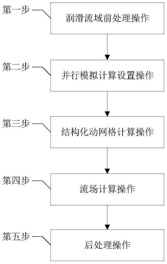
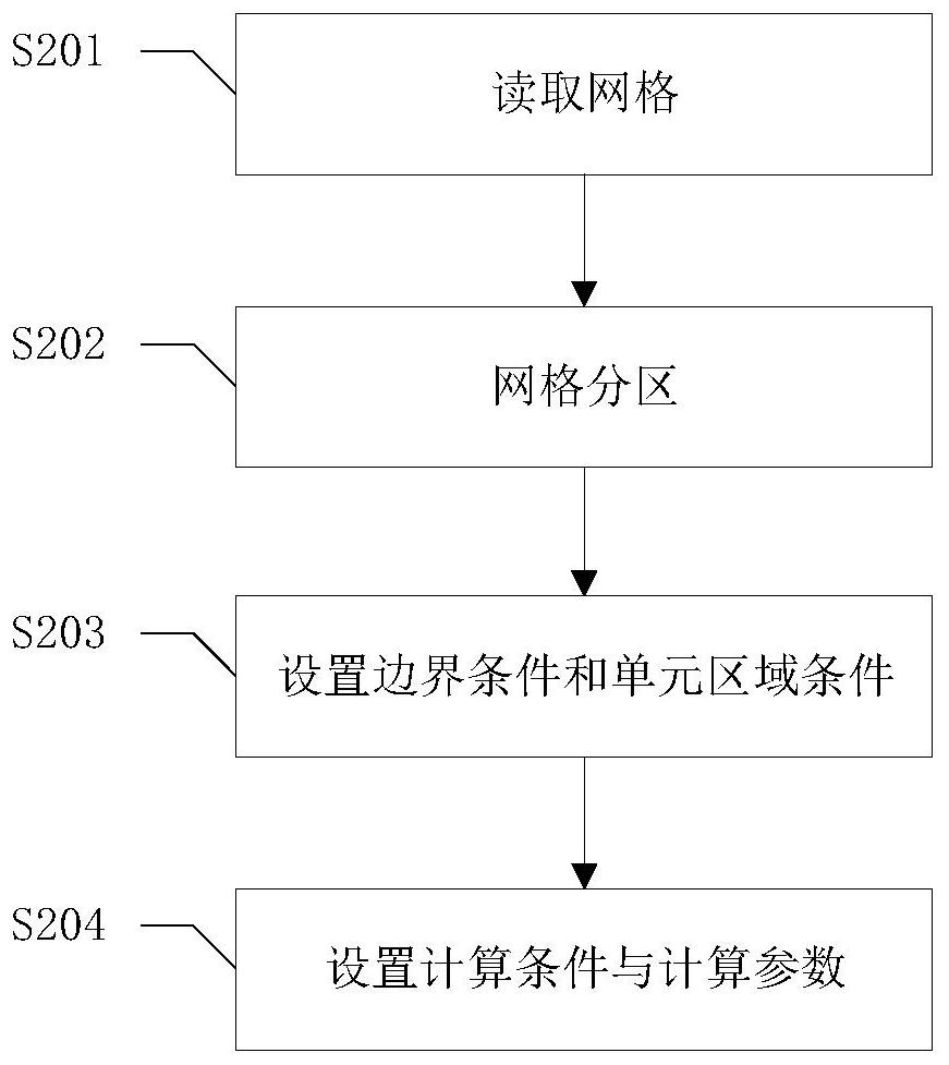
A method for parallel calculation of the dynamic grid in the lubrication water domain of a rotor-sliding bearing system, including pre-processing operations in the lubrication water domain, parallel simulation calculation setting operations, structured dynamic grid calculation operations, flow field calculation operations, and post-processing steps; rotor-sliding The dynamic grid parallel computing method of the lubrication flow domain of the bearing system realizes the multi-core parallel simulation of the lubrication flow domain of the high-speed rotor-sliding bearing system based on the structured dynamic grid in the parallel computing environment, and solves the problem of the original dynamic grid program in parallel computing. Due to the lack of data transmission, summary, and export functions in the environment, the problem that it cannot be applied to the parallel environment has realized accurate and efficient simulation of the rotor axis trajectory in the rotor-sliding bearing system, and overcomes the low simulation efficiency of the existing calculation methods. Low disadvantages can improve calculation efficiency while ensuring calculation accuracy, and predict the stability of high-speed rotor-bearing systems.

Description

technical field [0001] The invention relates to a parallel computing method for a dynamic mesh in a lubricated flow domain of a rotor-sliding bearing system, which belongs to the technical field of computational fluid dynamics simulation simulation. Background technique [0002] In the field of computational fluid dynamics (Computational Fluid Dynamics, CFD) simulation technology, serial computing can only rely on one thread in the processor to perform calculations. Waste of computing resources. Therefore, with the development of computational fluid dynamics simulation technology, the use of parallel technology has become a necessary means to improve the calculation speed of CFD. [0003] Centrifugal compressors, steam turbines, gas turbines and other high-speed rotating machinery are widely used in petrochemical, power engineering and other fields. This type of machinery has the characteristics of high operating speed and high working power, and is a key part of the entir...

Claims


Application Information

Patent Timeline
Patent Type & Authority Patents(China)
IPC IPC(8): G06F30/23G06F30/28G06F113/08G06F119/14
CPCG06F30/23G06F30/28G06F2113/08G06F2119/14Y02E10/20
Inventor 李强刘清磊唐心昊李斌许伟伟刘兆增王振波
Owner CHINA UNIV OF PETROLEUM (EAST CHINA)
Why Eureka
Try Eureka