Linear vibration generation device

a generation device and linear technology, applied in the direction of mechanical vibration separation, dynamo-electric machines, supports/enclosements/casings, etc., can solve the problems of inability to guarantee an extended lifespan, ineffective vibration performance, and inability to respond fast, so as to reduce the cost and the size of the plate, the effect of effective vibration performan

Active Publication Date: 2017-05-18
JAHWA ELECTRONICS
View PDF2 Cites 0 Cited by
  • Summary
  • Abstract
  • Description
  • Claims
  • Application Information

AI Technical Summary

Benefits of technology

[0016]Accordingly, the problem to be solved by the present invention is to provide a linear vibration generating device capable of securing a space which can obtain a sufficient stroke distance, that is, a sufficient amplitude, to cause a vibrator to oscillate without increasing a height of a case, thereby miniaturizing the device.
[0017]Another problem to be solved by the present invention is to provide a linear vibration generating device capable of preventing mechanical contact of components due to a pitching motion of a vibrator, and thus effectively decreasing a noise to be caused by the contact.

Problems solved by technology

Due to the popular propagation of cellular phones, noise pollution caused by incoming call ringtone leads to introduction of a new type of silence incoming call, such as vibration.
The above technology has drawbacks in that it does not guarantee an extended lifespan, the speed of response is not fast, and it is limited to various vibration modes.
Accordingly, with the trend in rapid popularization of a smartphone of a touch type, referred to as a touch phone, it is limited to meet the demand of users.
First, since the dampers are provided at inner upper and lower positions of the case, and the plates 113 and 114 having a desired thickness are provided on the top and bottom surfaces of the vibrator, it is not easy to secure a sufficient stroke distance, that is, an amplitude, so that the vibrator vibrates in the limited space of the case. As a result, the height of the case should be increased, which does not meet the miniaturization of the device. Also, the above-described related art has another problems of producing noise due to collision between the vibrator and the case, and being limited to thinning of the actuator due to the magnetic shield or the like.
Finally, in the process of generating vibrating the vibrator, since the vibrator undergoes lateral wobble, that is, pitching motion, as well as the vertical oscillation, an outer corner of the vibrator comes into directly contact with the case, which causes the noise to produce, thereby deteriorating the quality and reliability of the product.

Method used


Image

  • Linear vibration generation device
  • Linear vibration generation device
  • Linear vibration generation device

Examples


first embodiment

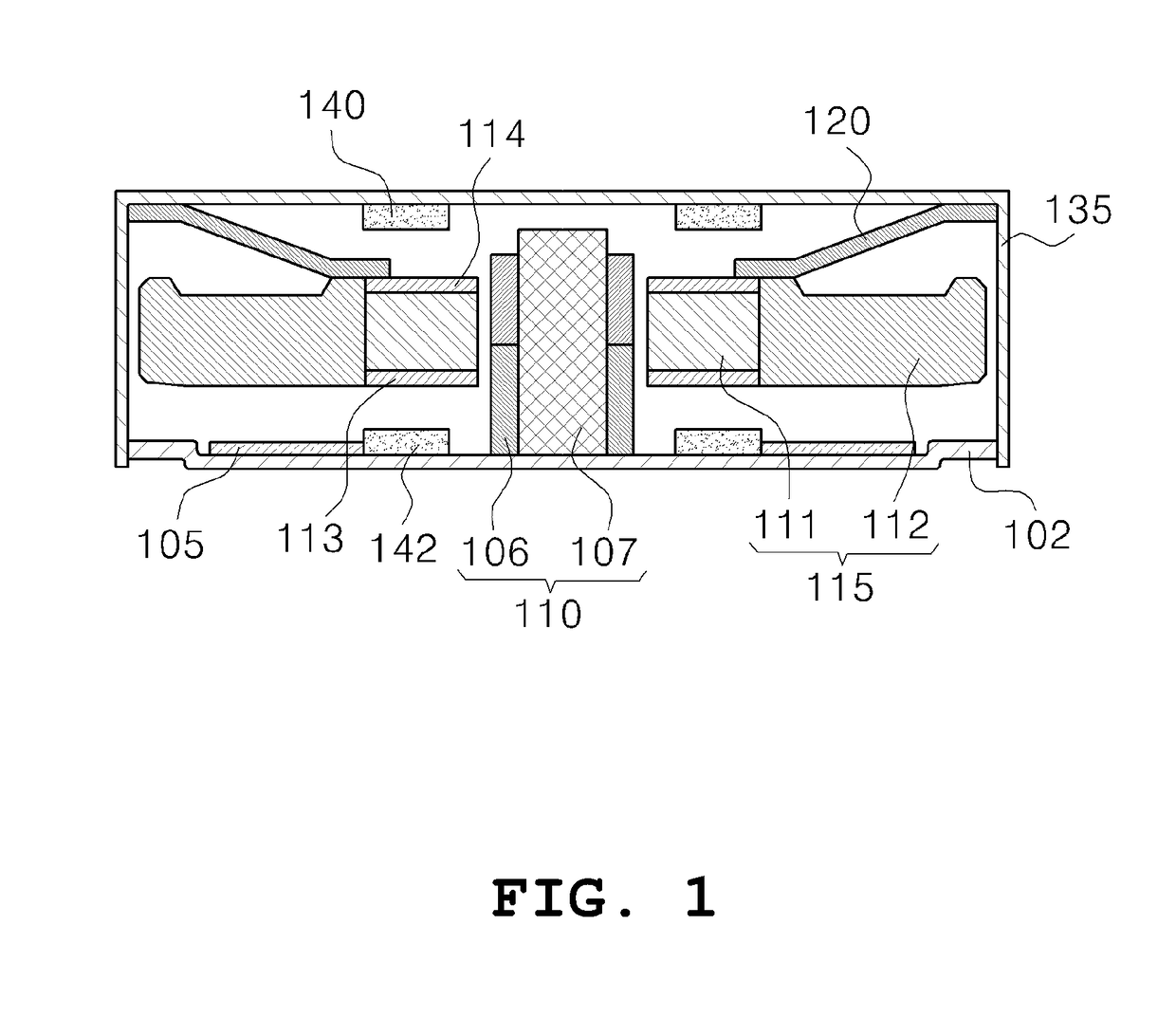
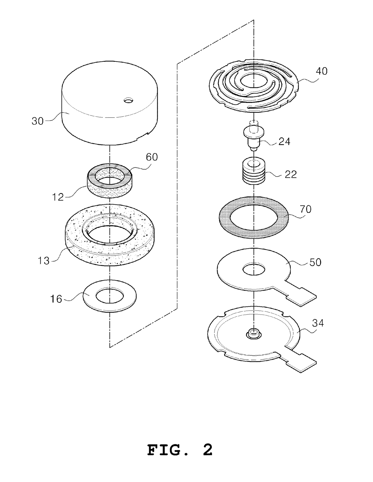
[0045]FIG. 2 is an exploded perspective view of a linear vibration generating device according to the present invention. FIG. 3 is a cross-sectional view illustrating an assembled state of the linear vibration generating device in FIG. 2. The whole configuration of the linear vibration generating device according to the present invention will now be described with the drawings.

[0046]Referring to FIGS. 2 and 3, the linear vibration generating device according to the present invention mainly includes a vibrator 10 and a stator 20. A resilient member 40 is interposed between the vibrator 10 and the stator 20 to resiliently support vertical oscillation of the vibrator 10, and a PCB 50 for supplying an AC power to generate the oscillation is provided on a planar bracket 34 constituting the stator 20.

[0047]The vibrator 10 has a permanent magnet 12 for forming a magnetic field and a weight 13 engaged to the permanent magnet 12 in such a manner of enclosing the permanent magnet 12 to apply ...

second embodiment

[0055]One end of the resilient member 40 is welded to the bottom surface of the plate 16, and an opposite end is welded to an edge of the top surface of the bracket 34. Of course, both ends of the resilient member may be welded to the top surface of the plate and one surface of the upper case facing the top surface in the configuration of which the plate is placed on the top surface of the vibrator (see the second embodiment described later), respectively.

[0056]If an inner peripheral surface 13 of an inner fixing end 44 of the resilient member 40 which is brought into contact with the plate 16 is arranged on the same line as an inner peripheral surface 12 of the plate 16, it is possible to maximize the length of a driving portion (referred to as a spring foot 43) of the resilient member which connects an outer fixing end 42 and the inner fixing end 44 of the resilient member 40 in the limited space, thereby simplifying a pattern of the driving portion 43.

[0057]The linear vibration g...


PUM


Abstract

Disclosed is a linear vibration generating device including: a stator including a bracket on which a coil is seated, and a case made of a magnetic material which is engaged to the bracket to form an inner space; a vibrator including a permanent magnet for generating a vibration force in cooperation with the coil, and a weight enclosing a circumference of the permanent magnet; a resilient member which is positioned between the vibrator and the stator to resiliently support vertical oscillation of the vibrator; and a plate which is positioned between the resilient member and the vibrator.

Description

CROSS-REFERENCE TO RELATED APPLICATIONS[0001]This application is a Divisional Application of U.S. Ser. No. 15 / 049,569 filed on Feb. 22, 2016, which is a continuation of International Application No. PCT / KR2014 / 010576 filed on Nov. 5, 2014, which claims priority to Korean Application No. 10-2013-0134890 filed on Nov. 7, 2013, which applications are incorporated herein by reference.TECHNICAL FIELD[0002]The present invention relates to a linear vibration generating device, and more particularly, to a linear vibration generating device capable of generating a vibration by use of repeatedly vertically linear movement of a weight which is caused by interaction between an electric field generated by a coil and a magnetic field generated by a permanent magnet.BACKGROUND ART[0003]Due to the popular propagation of cellular phones, noise pollution caused by incoming call ringtone leads to introduction of a new type of silence incoming call, such as vibration. Such a new type of silence incomin...

Claims


Application Information

Patent Timeline
Patent Type & Authority Applications(United States)
IPC IPC(8): H02K33/16H02K5/02
CPCH02K5/02H02K33/16B06B1/04H02K33/02H02K33/00
Inventor SHIM, SOON KOOCHONG, YOUNG BINCHOI, NAM JINLEE, MIN GOO
Owner JAHWA ELECTRONICS
Why Eureka
Try Eureka