Floating patella sensor, knee stabilizer with same and robotic knee testing apparatus with same

a technology of knee stabilizer and patella sensor, which is applied in the field of floating patella sensor for joint stabilizer, can solve the problems of damage to one or more structures, inability to quantify the increase or decrease in joint play of the knee with limited success, and inability to accurately measure the impact of the knee. , to achieve the effect of accurate, objective, reliable and/or reproducible measurement of the impa

Active Publication Date: 2017-05-25
ERMI
View PDF8 Cites 8 Cited by
  • Summary
  • Abstract
  • Description
  • Claims
  • Application Information

AI Technical Summary

Benefits of technology

[0018]Accordingly, there is a need for an improved, i.e., accurate, objective, reliable and / or reproducible measure of the impact of damage or injury to the knee, as well as other joints. Such injuries or damage to the knee can be to the ACL as well as other ligaments and structures in the knee or combination of ligaments and other structures in the knee. The improved measure can be used in the clinical setting on patients. For example, since an injury to the ACL produces both an increase in anterior translation (y-axis translation) and rotation (z-axis rotation), an objective measure of these changes would both aid in the diagnosis of the injury and aid in verifying restoration of the joint after ligament reconstruction surgery. Also, the improved measurement of displacement and compliance around different degrees of freedom in the knee would help objectively describe the individual and complex changes to ‘joint play’ that occur in an injured knee with structural damage. A need exists for systems and methods that can provide accurate, reproducible and objective data on the changes in ‘joint play’ or motion that occur with an injured knee compared to a healthy knee. The improved systems and methods can also provide data that can be compared to data from the general population. As a result, the clinician can achieve patient satisfaction with focused, biomechanical, and proven surgical interventions specific to a given injured joint, and for that knee or joint to be compared across an entire data set of damaged knees or joints.

Problems solved by technology

When this joint play is increased, or decreased, an abnormal or pathological condition exists in the knee.
Attempts have been made in the past to quantify this increase or decrease in joint play of the knee with limited success.
Knee injuries often cause damage to one or more of the structures that form the knee joint.
Such injuries typically cause an increase in joint play or motion of the knee.
Knee instability may also be related in part to the shape and size of the joint bones.
Because these tests are performed manually by individual medical personnel, these tests naturally are limited by the specific clinician's subjective evaluation.
The subjective nature of the tests may hinder the precision or accuracy of any diagnosis of the extent of ligament lengthening, the change in ligament compliance or elastic resilience, i.e., stretchiness, or both.
The Pivot Shift test is inherently subjective, difficult to accurately perform, difficult to teach, and ultimately difficult to quantify.
A misdiagnosis can lead to unnecessary treatment or unnecessary delay in treatment, which may result in an increased risk for further injury or damage to the patient's knee joint.
Also, a knee joint may have injury or damage to more than one ligament or structure.
The more ligaments and structures of the knee joint that are damaged, the more complex it is for the clinician to perform a manual knee examination.
This can make the diagnosis less accurate and less precise.
However, due to the variability in size of the patient, size and experience of the surgeon, and the potential degree or subtlety of an injury, consistent and reproducible reports of joint play between surgeons is not possible.
This results in inconsistencies in the examination of joint play.
The KT devices do not measure relative displacement or compliance in any of the other degrees of freedom in the knee.
Also, quantified results from using the KT devices have not been correlated with patient satisfaction.
However, numerous published reports have documented significant measurement error related to skin artifact with such systems.
However, sometimes, medical imaging systems are not a viable option, such as for testing and evaluating joint play utilizing various joint play manipulation and evaluation devices and apparatuses.

Method used


Image

  • Floating patella sensor, knee stabilizer with same and robotic knee testing apparatus with same
  • Floating patella sensor, knee stabilizer with same and robotic knee testing apparatus with same
  • Floating patella sensor, knee stabilizer with same and robotic knee testing apparatus with same

Examples


Embodiment Construction

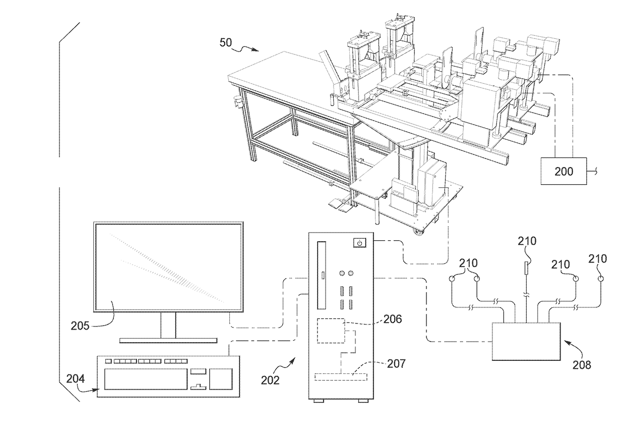
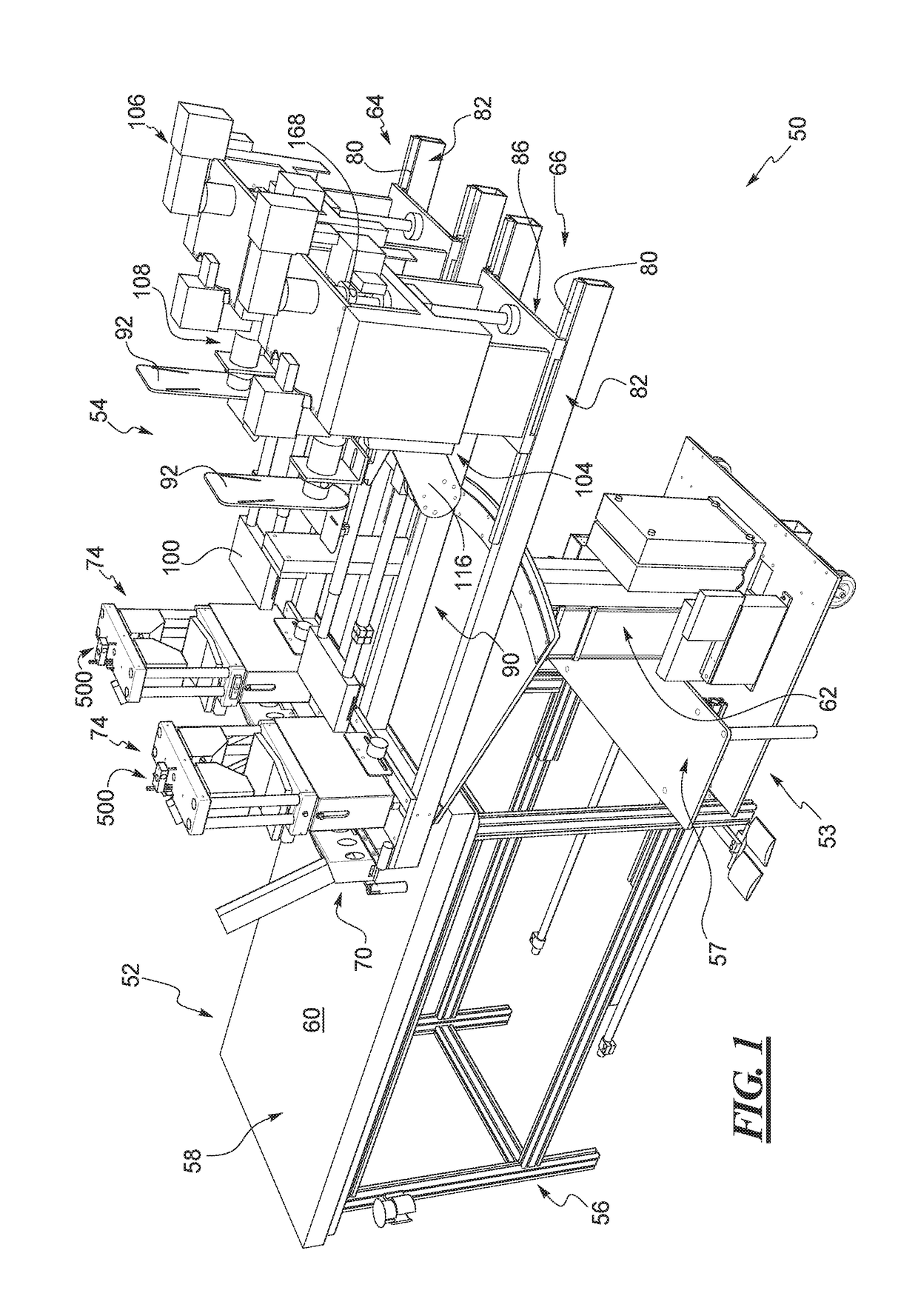
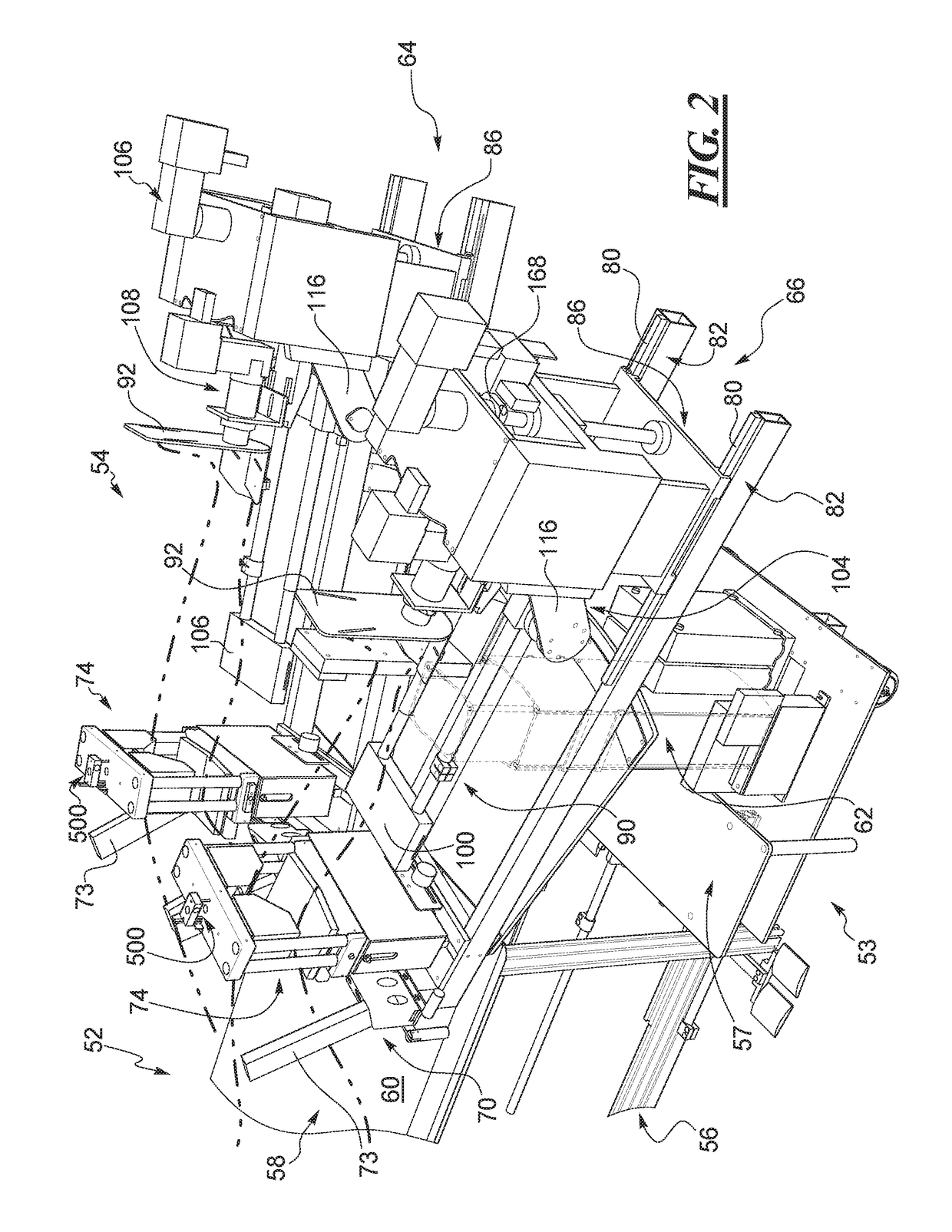
[0057]The disclosed floating patella sensor, knee or patellar stabilizer, and robotic knee testing (RKT) apparatus (i.e., one form of a joint manipulation and evaluation apparatus) solve or improve upon one or more of the above noted and / or other problems and disadvantages with prior known knee testing devices. In particular, the disclosed knee stabilizer and RKT apparatus utilize a floating sensor that determines the degree of residual femur movement during knee testing while the femur and patella are held in place by the knee stabilizer. The floating sensor can be connected to a processor of the RKT apparatus or an external computer. Data obtained by the floating sensor related to such residual movement of the femur and patella can then be used within the processor to account for such residual movement in the diagnosis of the knee joint. The disclosed floating sensor, stabilizer, and evaluation apparatus can also be further developed and used to evaluate joints other than knee joi...


PUM


Abstract

A joint manipulation and evaluation apparatus has a mechanism configured to manipulate a first bone of a joint relative to a second bone of the joint. The apparatus has a joint stabilizer arranged to engage the joint and hold the second bone in place as the first bone is manipulated. A sensor is coupled to the joint stabilizer and is configured and arranged to detect residual movement of a clamped portion of the joint relative to the joint stabilizer as the first bone is manipulated.

Description

RELATED APPLICATION DATA[0001]This patent is related to and claims priority benefit of U.S. Provisional Application Ser. No. 62 / 258,191 filed on Nov. 20, 2015 and entitled “Floating Patella Sensor, Knee Clamp with Floating Patella Sensor, and Robotic Knee Testing Device with Same.” The entire contents of this prior filed application are hereby incorporated herein by reference.BACKGROUND[0002]1. Field of the Disclosure[0003]The disclosure generally relates to a joint manipulation and evaluation apparatus, and more particularly to a floating sensor for a joint stabilizer of such an apparatus.[0004]2. Description of Related Art[0005]The knee joint is composed of the femur or thigh bone, the tibia or shin bone, and the patella or knee cap. The bones are connected by fibrous structures called ligaments, which allow a certain amount of “joint play” or motion to exist between the bone structures. When this joint play is increased, or decreased, an abnormal or pathological condition exists ...

Claims


Application Information

Patent Timeline
Patent Type & Authority Applications(United States)
IPC IPC(8): A61B5/00A61B5/11
CPCA61B5/4585A61B5/4528A61B34/30A61B5/11A61B5/6884A61B5/702A61B5/1121A61B6/0421A61B6/00
Inventor BRANCH, THOMAS P.STINTON, SHAUN K.DITTMAR, EDWARDDEJARNETTE, NATHANIEL K.MADDEN, T. CHRISTOPHER
Owner ERMI
Why Eureka
Try Eureka