Blade set, hair cutting appliance, and related manufacturing method

a technology of blade set and blade set, which is applied in the direction of metal working devices, etc., can solve the problem of limiting the minimum cutting length, achieve the effect of reducing the time required for cutting operations, improving operating performance, and satisfying user experience in shaving and trimming operations

Active Publication Date: 2017-05-25
KONINKLJIJKE PHILIPS NV
View PDF19 Cites 29 Cited by
  • Summary
  • Abstract
  • Description
  • Claims
  • Application Information

AI Technical Summary

Benefits of technology

[0014]It is an object of the present disclosure to provide an alternative stationary cutter blade, and a corresponding blade set that enables both shaving and trimming. In particular, a stationary blade and a blade set may be provided that contribute to a pleasant user experience in both shaving and trimming operations. More preferably, the present disclosure may address at least some drawbacks inherent in known prior art hair cutting blades as discussed above, for instance. It would be further advantageous to provide for a blade set that may exhibit an improved operating performance while preferably reducing the time required for cutting operations. It is further preferred to provide for a corresponding method for manufacturing such a stationary blade. It is particularly desired to present a manufacturing method that may permit the production of blade sets and particularly of stationary blades in a cost-efficient manner and with appropriate process capability.

Problems solved by technology

However, a required minimum thickness of the first wall portion basically limits the minimum cutting length.
However, this does not necessarily exclude that the plastic component is also at least partially molded to the first wall portion or to a transition between the first wall portion and the second wall portion.

Method used


Image

  • Blade set, hair cutting appliance, and related manufacturing method
  • Blade set, hair cutting appliance, and related manufacturing method
  • Blade set, hair cutting appliance, and related manufacturing method

Examples


Embodiment Construction

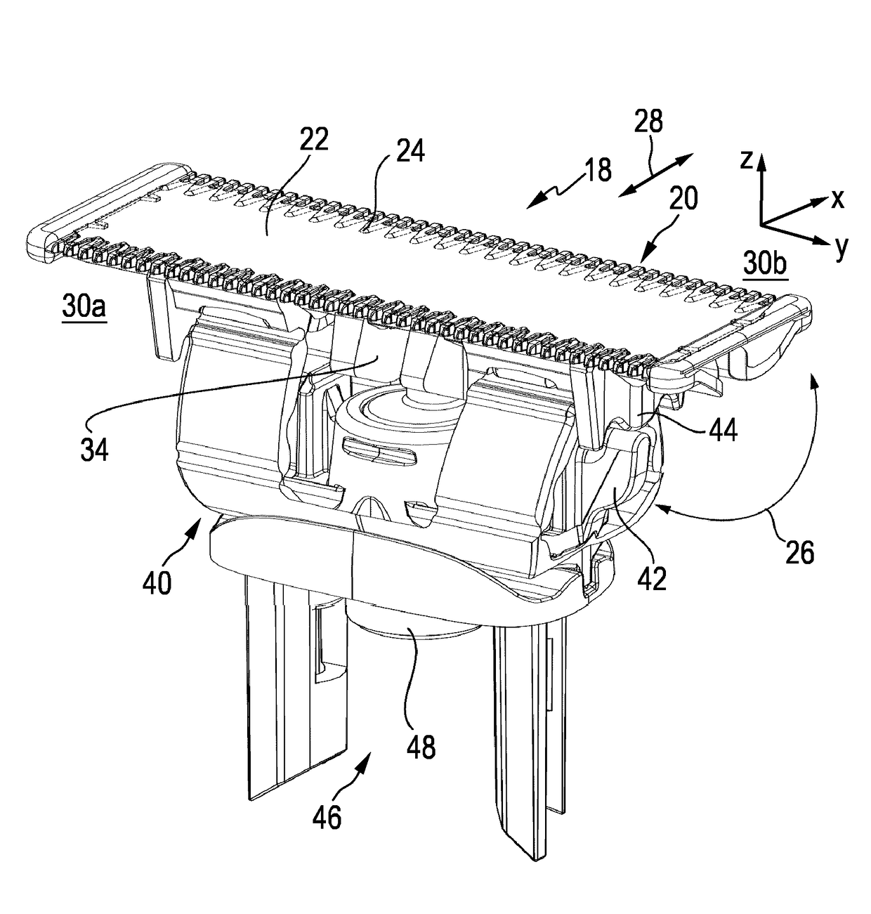
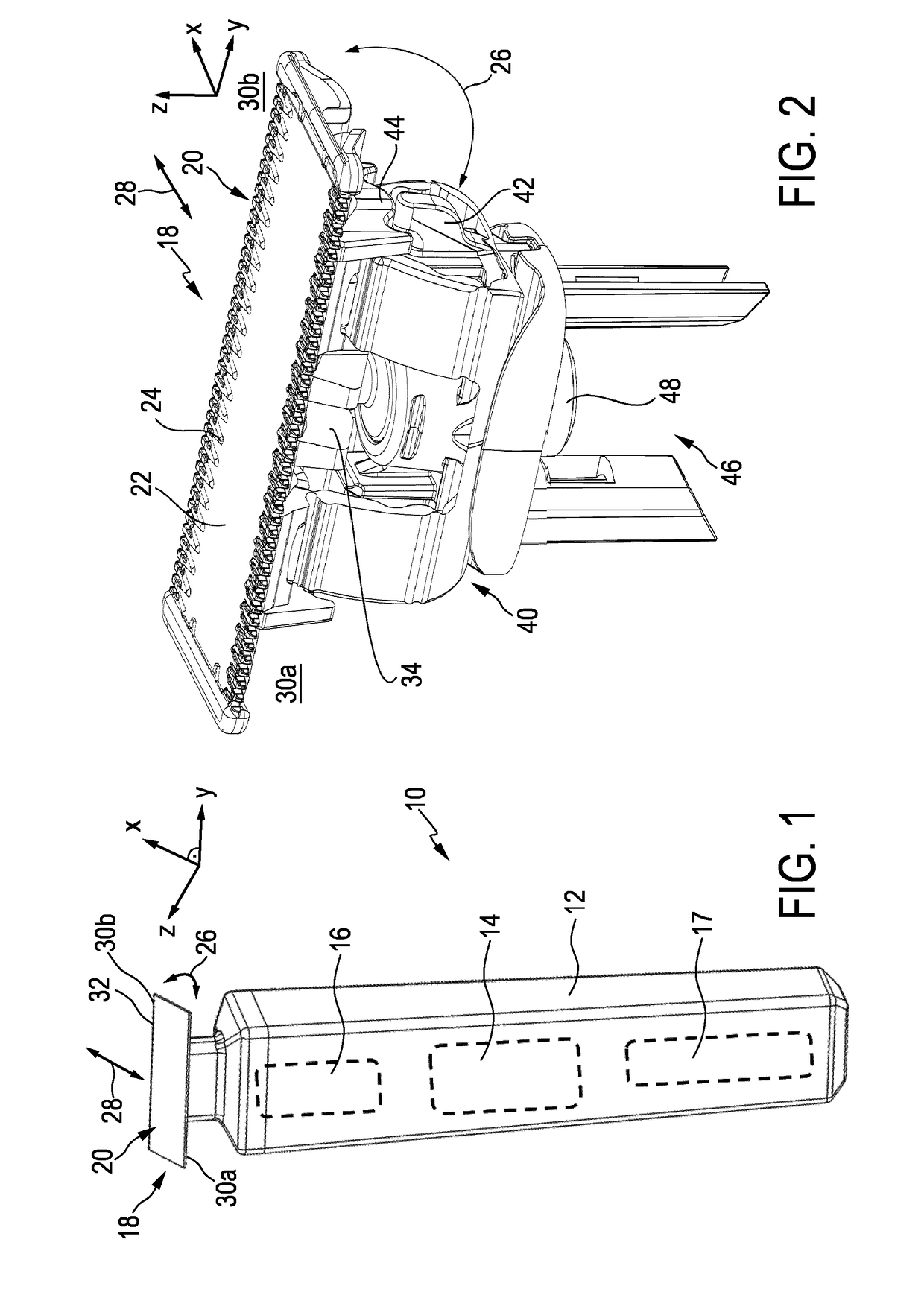
[0093]FIG. 1 schematically illustrates, in a simplified perspective view, an exemplary embodiment of a hair cutting appliance 10, particularly an electric hair cutting appliance 10. The cutting appliance 10 may comprise a housing or, more particularly, a housing portion 12, a motor indicated by a dashed block 14 in the housing portion 12, and a drive mechanism or drivetrain indicated by a dashed block 16 in a housing portion 12. For powering the motor 14, at least in some embodiments of the cutting appliance 10, an electrical battery, indicated by a dashed block 17 in the housing portion 12, may be provided, such as, for instance, a rechargeable battery, a replaceable battery, etc. However, in some embodiments, the cutting appliance 10 may be further provided with a power cable for connecting a power supply. A power supply connector may be provided in addition or in the alternative to the (internal) electric battery 17.

[0094]The cutting appliance 10 may further comprise a cutting he...


PUM


Abstract

The present disclosure relates to a hair cutting appliance (10), a blade set (20) for a hair cutting appliance (10),and to an integrally formed metal-plastic composite stationary blade (22) for said blade set (20). Said stationary blade (22) may comprise a first wall portion (58) arranged to serve as a skin facing wall when in operation, a second wall portion (60) at least partially offset from the first wall portion (58), such that the first wall portion (58) and the second wall portion (60) define therebetween a guide slot arranged to receive a movable cutter blade (24), at least one toothed leading edge (30) jointly formed by the first wall portion (58) and the second wall portion (60), and a plastic component (114) comprising at least one mounting element (36), wherein the at least one toothed leading edge (30) comprises a plurality of teeth (90), wherein the first wall portion (58) and the second wall portion (60) are integrally made from a metal component (56), particularly from a sheet metal component (56), wherein the first wall portion (58) and the second wall portion (60) mutually define an inner metal shell of the stationary blade (22), and wherein the plastic component (114) is molded to the second wall portion (60). The disclosure further relates to a method for manufacturing a respective blade.

Description

FIELD OF THE INVENTION[0001]The present disclosure relates to a hair cutting appliance, particularly to an electrically operated hair cutting appliance, and more particularly to a stationary blade of a blade set for such an appliance. The blade set may be arranged to be moved through hair in a moving direction to cut hair. The stationary blade may comprise a first wall portion and a second wall portion that define therebetween a guide slot, where a movable cutter blade may be at least partially encompassed and guided. The present disclosure further relates to a method for manufacturing a stationary blade and a blade set for a hair cutting appliance.BACKGROUND OF THE INVENTION[0002]GB 2 266 259 A discloses a hair trimmer for the nose or ears, comprising a body serving as a handle and having an extension for insertion in the nose or ear with cutting means at its distal end, said cutting means comprising reciprocally movable blade means slidably engaging an anvil having at least one ap...

Claims


Application Information

Patent Timeline
Patent Type & Authority Applications(United States)
IPC IPC(8): B26B19/38B26B19/06B26B19/20
CPCB26B19/3846B26B19/063B26B19/20B26B19/3893B26B19/042
Inventor SABLATSCHAN, SIEGFRIED
Owner KONINKLJIJKE PHILIPS NV
Why Eureka
Try Eureka