
Gearbox Having an Electric Motor

a technology of electric motors and gearboxes, applied in the direction of gearboxes, mechanical equipment, transportation and packaging, etc., can solve the problems of inefficiency in the installation space and construction cost of transmissions, and achieve the effect of cost-effectiveness

Active Publication Date: 2017-05-25
ZF FRIEDRICHSHAFEN AG
View PDF3 Cites 3 Cited by
  • Summary
  • Abstract
  • Description
  • Claims
  • Application Information

AI Technical Summary

Benefits of technology

The invention is a transmission that saves space and is easy to produce, making it the most cost-effective transmission possible. Its design includes planetary gear sets and shifting elements arranged in a way that reduces the amount of space needed for installation and reduces production costs.

Problems solved by technology

Frequently, however, the transmissions are not designed for efficiency in terms of installation space and construction costs, but, by the transmission schemes, only specify a schematic arrangement that leaves opens the exact arrangement of the transmission elements in space and relative to each other.

Method used


Image

  • Gearbox Having an Electric Motor
  • Gearbox Having an Electric Motor
  • Gearbox Having an Electric Motor

Examples


Embodiment Construction

[0054]Reference will now be made to embodiments of the invention, one or more examples of which are shown in the drawings. Each embodiment is provided by way of explanation of the invention, and not as a limitation of the invention. For example, features illustrated or described as part of one embodiment can be combined with another embodiment to yield still another embodiment. It is intended that the present invention include these and other modifications and variations to the embodiments described herein.

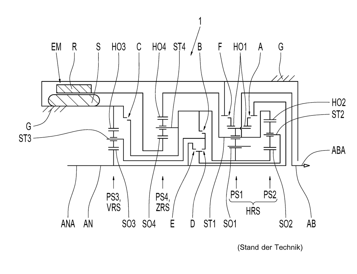
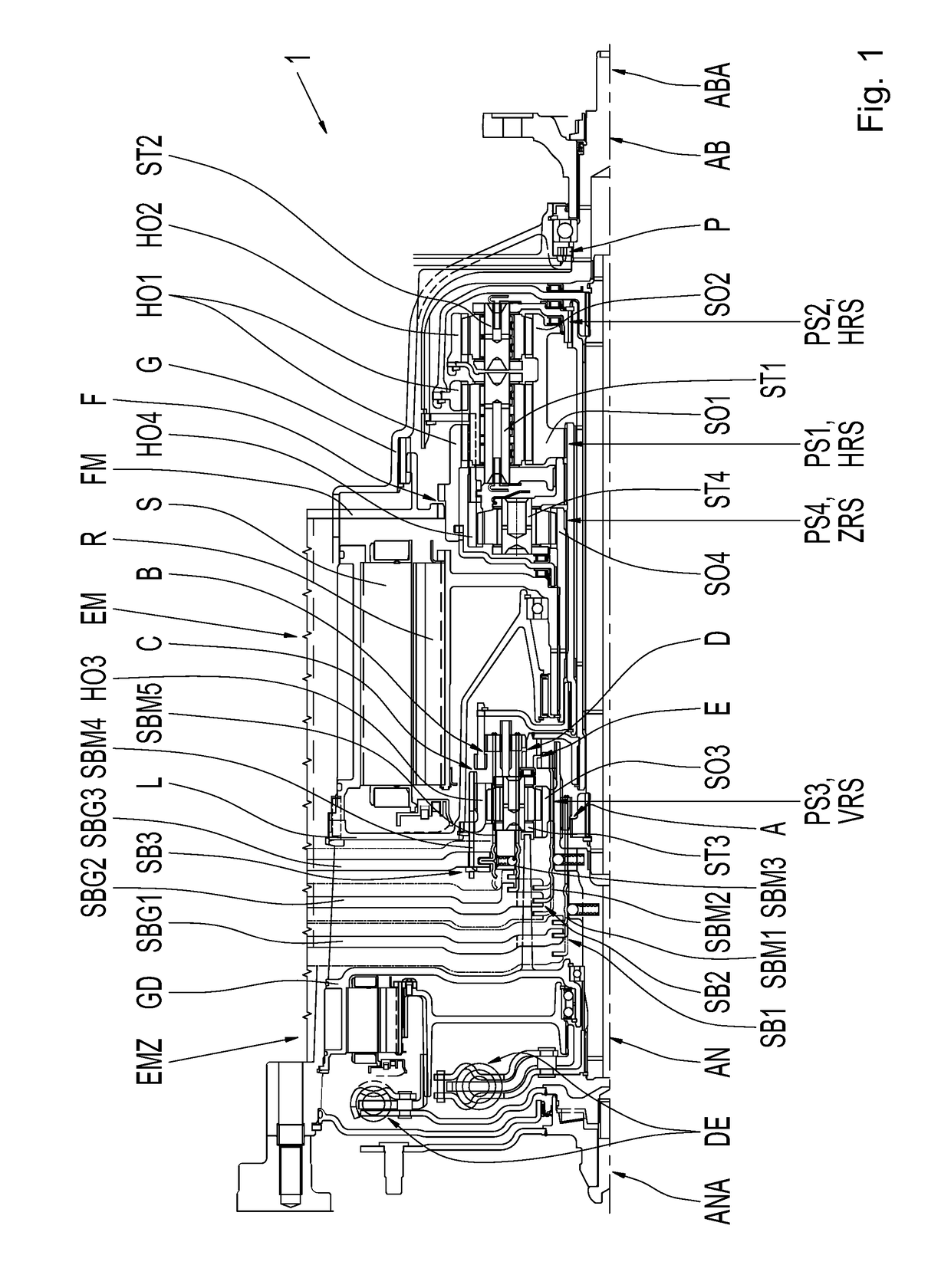
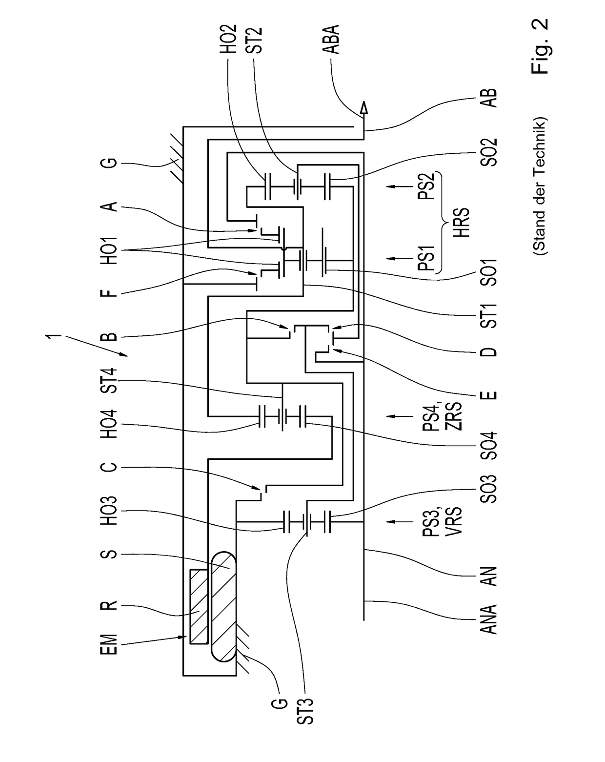
[0055]FIG. 1 shows a sectional view of an embodiment of a transmission 1. The transmission 1 is shown in a longitudinal section, whereas, based on the rotational symmetry, only a transmission section split at the center axis of the transmission 1 is shown. Here, the center axis of the transmission 1 is shown as a dash-dot line. The transmission 1 features a drive shaft AN that runs along the center axis, the center axis also constitutes the axis of rotation of the drive shaft AN. ...


PUM


Abstract

A transmission includes an electric motor arranged between a drive shaft connection area and an output shaft connection area. The electric motor encloses a cylindrical volume. A first group of shifting elements is arranged adjacent to and axially along a drive shaft in the direction of the drive shaft connection area offset to the electric motor or is at least partially arranged within the cylindrical volume of the electric motor. Shift forks of the first group of shifting element actuators are arranged adjacent to and axially along the drive shaft in the direction of the drive shaft connection area offset to the first group of shifting elements. A main gear set is arranged at least partially within the cylindrical volume of the electric motor or adjacent to axially along the drive shaft in the direction of the output shaft connection area offset to the electric motor.

Description

FIELD OF THE INVENTION[0001]The present invention relates generally to a transmission with an electric motor for a drive train of a vehicle.BACKGROUND[0002]It is frequently the case that a transmission that is employed in the drive train of a vehicle has planetary gear sets that can be connected to each other by shifting elements, for example clutches, in order to realize different transmission ratio relationships between a drive shaft of the transmission and an output shaft of the transmission. The transmission includes a predefined number of stepped gears. Typically, a starting element (which can be, for example, a hydrodynamic or electrodynamic starting element) can be coupled to the planetary gear sets.[0003]Various transmissions with an electric motor are known from the state of the art, with which the electric motor can be connected to an output shaft of the transmission, either directly or through a planetary gear set, with a fixed transmission ratio and / or by a shifting elem...

Claims


Application Information

Patent Timeline
IPC IPC(8): B60K6/365B60K6/40B60K6/547F16H3/72B60K6/26B60K6/48
CPCB60K6/365B60K6/26B60K6/48B60K6/547F16H2200/2012B60K6/40B60K2006/4816F16H2200/2007F16H2200/201F16H3/724B60K6/36
Inventor ZIEMER, PETER
Owner ZF FRIEDRICHSHAFEN AG
Learn More