
Container provided with a curved invertible diaphragm

a technology of invertible diaphragm and container, which is applied in the field of container manufacturing, can solve the problems of bending of containers, reducing the stability of the pressure panel, so as to achieve greater stability

Active Publication Date: 2017-05-25
SIDEL PARTICIPATIONS SAS
View PDF10 Cites 4 Cited by
  • Summary
  • Abstract
  • Description
  • Claims
  • Application Information

AI Technical Summary

Benefits of technology

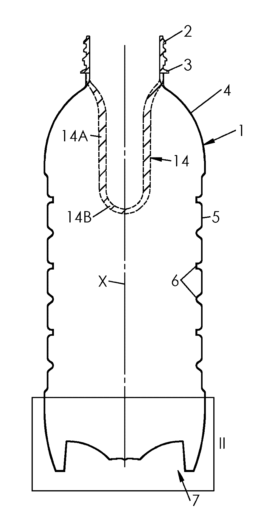
The patent is about a diaphragm in a container that keeps the pressure high and rigid, even when the container is placed in an inverted position. This is achieved by using a rigid inner portion of the diaphragm that prevents it from collapsing back into the container. This results in a highly rigid container that maintains its shape and pressure.

Problems solved by technology

Tests conducted on such a container showed that, once inverted to the inwardly-inclined position, the pressure panel does not maintain its position but tends to sink back under the pressure of the content.
When stacking or palletizing the containers, there is a risk for the lower containers to bend under the weight of upper containers, and hence a risk for the whole pallet to collapse.

Method used


Image

  • Container provided with a curved invertible diaphragm
  • Container provided with a curved invertible diaphragm
  • Container provided with a curved invertible diaphragm

Examples


first embodiment

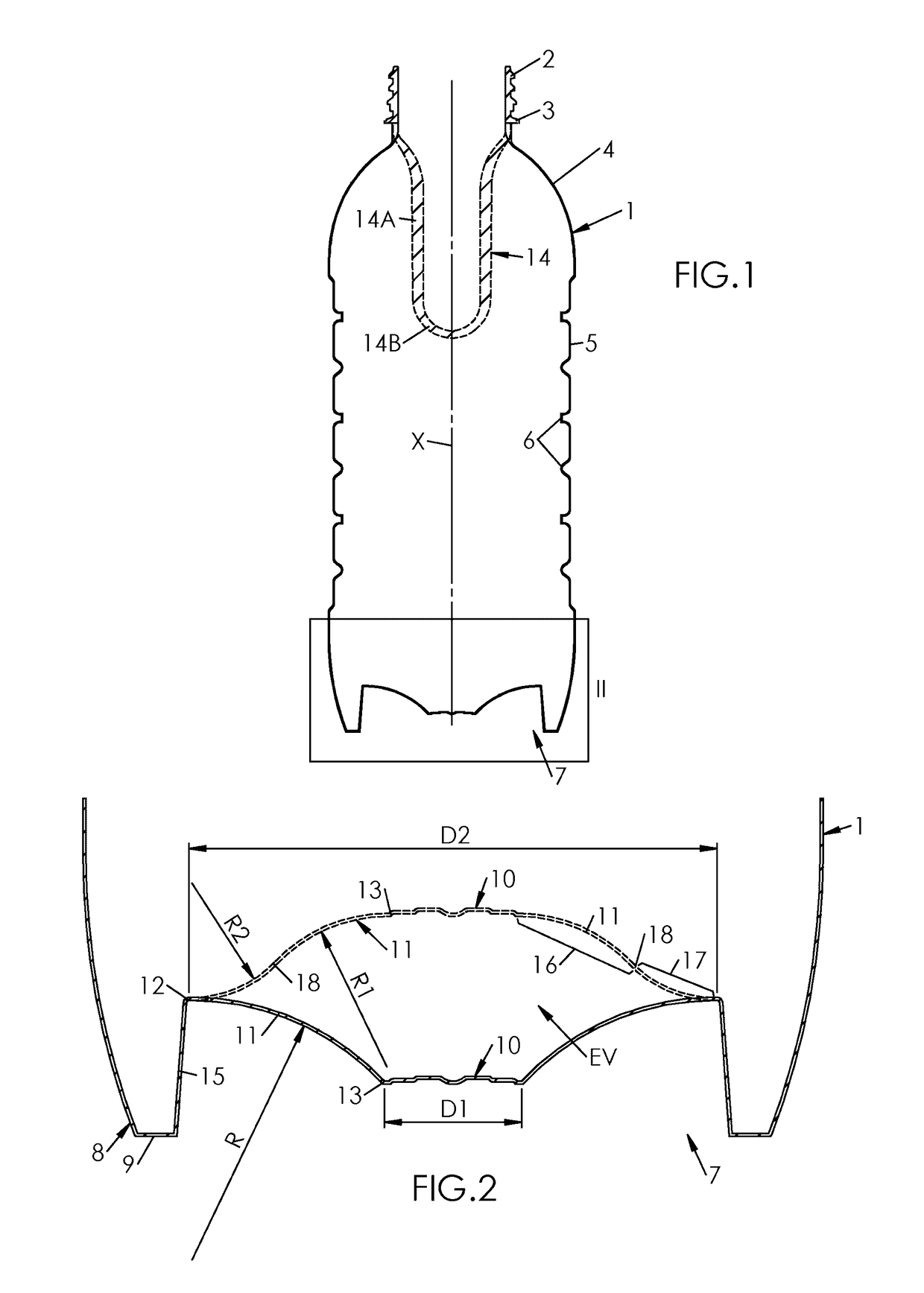
[0046]In a first embodiment illustrated on FIG. 2, the diaphragm 11 has, in the outwardly-inclined position, a radius of curvature—denoted R—which is constant or substantially constant from the outer junction 12 to the inner junction 13.

[0047]In a preferred embodiment, R is of about half the outer diameter D2 of the diaphragm 11:

R≅D22

[0048]In the embodiment depicted on FIG. 2, a tangent of the diaphragm 11 to the outer junction 12 is horizontal, i.e. perpendicular to the main axis X of the container 1, in the outwardly-inclined position.

[0049]During inversion, the tangent maintains its orientation. Therefore, in the inwardly-inclined position, the diaphragm 11 has an outer portion 17, adjacent to the outer junction 12, which is also curved in radial section, but with a concavity turned inwards with respect to the container 1. In FIG. 2, R2 denotes the radius of curvature of the outer portion 17. The inner portion 16 and the outer portion 17 meet at a median junction 18 which, in rad...

second embodiment

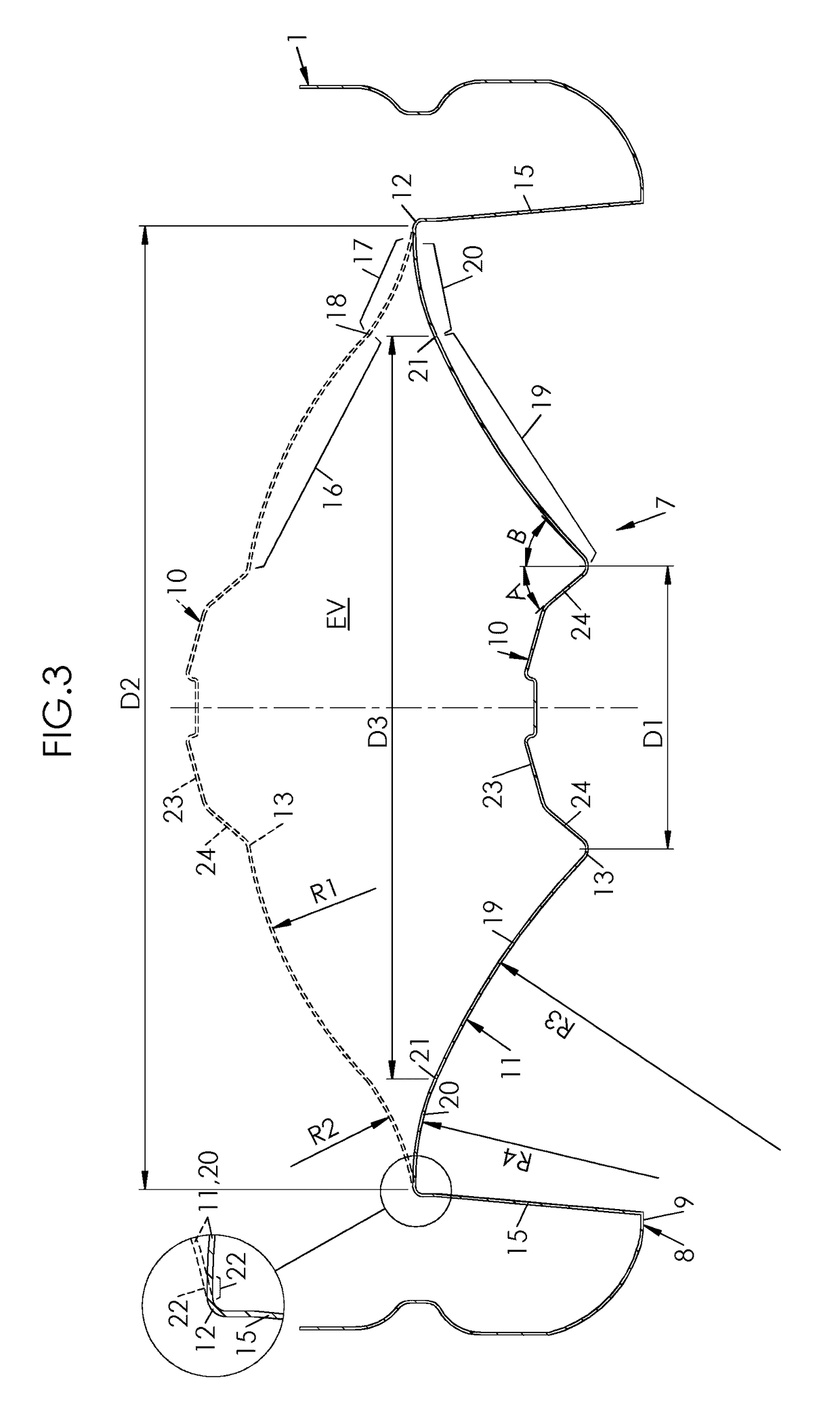
[0050]In a second embodiment illustrated on FIG. 3, the radius of curvature of the diaphragm 11 has, in the outwardly-inclined position, at least two values. More specifically, the diaphragm 11 has, in the outwardly-inclined position:[0051]an inner portion 19 which, in radial section, is curved with a concavity turned outwards with respect to the container 1, with a radius of curvature denoted R3, and[0052]an outer portion 20 which, in radial section, is curved with a concavity turned outwards with respect to the container 1, with a radius of curvature denoted R4, smaller than R3:

R4≦R3

[0053]More precisely, R3 and R4 are preferably such that their ratio is comprised between about 0.2 and 1, and more preferably of about 0.30, as depicted on FIG. 3:

0.2≤R3R4≤1

and, preferably:

R3R4≅0.3

[0054]In addition, the inner portion 19 and the outer portion 20 connect at a circular junction 21 having a diameter, denoted D3, such that the ratio of D3 and D2 is comprised between 0.5 and 1, and preferab...


PUM


Abstract

Disclosed is a Container (1) made of a plastic material, provided with a base (7) including a standing ring (8) forming a support flange (9) and a diaphragm (11) extending from the standing ring (8) to a central portion (10), the diaphragm (11) being capable of standing in an outwardly-inclined position. The diaphragm (11) connects to the standing ring (8) at an outer junction (12) forming an outer articulation of the diaphragm (11). The diaphragm (11) connects to the central portion (10) at an inner junction (13) forming an inner articulation of the diaphragm (11). The diaphragm (11) is invertible with respect to the standing ring (8) from the outwardly-inclined position to an inwardly-inclined position. In the inwardly-inclined position, at least an inner portion (16) of the diaphragm (11) adjacent to the inner junction (13) is curved in radial section, with a concavity turned outwards.

Description

FIELD OF THE INVENTION[0001]The invention generally relates to the manufacturing of containers, such as bottles, which are produced by blow molding or stretch-blow molding from preforms made of plastic (mostly thermoplastic, e.g. PET) material. More specifically but not exclusively, the invention relates to the processing of hot-fill containers, i.e. containers filled with a hot pourable product (typically a liquid), the term “hot” meaning that the temperature of the product is greater than the glass transition temperature of the material in which the container is made. Typically, hot filling of PET containers (the glass transition temperature of which is of about 80° C.) is conducted with products at a temperature comprised between about 85° C. and about 100° C., typically at 90° C.BACKGROUND OF THE INVENTION[0002]U.S. Pat. Appl. No. 2008 / 0047964 (Denner et al, assigned to CO2PAC) discloses a container comprising a pressure panel located in the bottom portion of the container.[0003...

Claims


Application Information

Patent Timeline
IPC IPC(8): B65D79/00B65D1/44B65D1/02
CPCB65D79/005B65D1/0276B65D1/0207B65D1/44B65D1/0246B65D79/0081
Inventor GODET, FLORIANPIERRE, IVAN
Owner SIDEL PARTICIPATIONS SAS
Learn More