Detection method and detection device

a detection method and detection device technology, applied in magnetic separation, biochemistry apparatus and processes, instruments, etc., can solve the problem of difficult to detect the detection target substance with substantial precision, and achieve the effect of accurate detection and fixed fixation

Active Publication Date: 2017-05-25
SYSMEX CORP
View PDF1 Cites 1 Cited by
  • Summary
  • Abstract
  • Description
  • Claims
  • Application Information

AI Technical Summary

Benefits of technology

[0016]In the detection method of the embodiment, the magnetic particles can be positioned at the interior surface in a state in which overlapping is suppressed similar to the third embodiment. The interior surface also has a surface charge that is opposite the charge of the magnetic particles. Therefore, the detection target substance bound to the magneti...

Problems solved by technology

It is therefore difficult to detect the dete...

Method used


Image

  • Detection method and detection device
  • Detection method and detection device
  • Detection method and detection device

Examples


first embodiment

[0060]The first embodiment is a detection method to detect a detection target substance bound to magnetic particles, and the invention is applied to a method to detect target DNA bound to magnetic particles. The first embodiment is a method related to the detection process. When the process performed prior to the detection process is referred to as a “pre-process”, the target DNA molecules are detected from the liquid suspension manufactured in the pre-process.

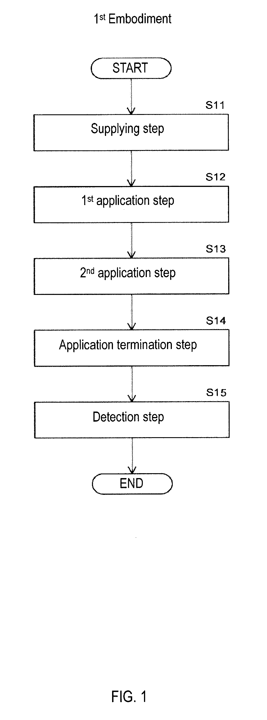
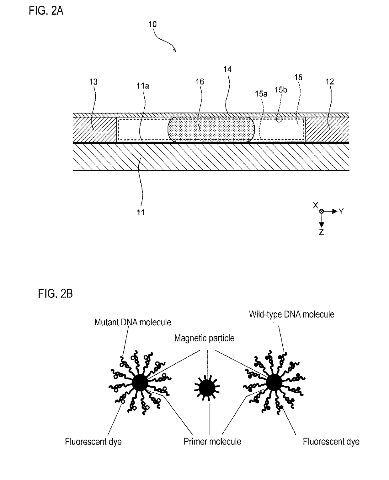
[0061]As shown in FIG. 1, the detection method to detect a detection target substance includes a supplying step, first application step, second application step, application termination step, and detection step. A container 10 shown in FIG. 2 (a) is prepared prior to performing these steps.

[0062]As shown in FIG. 2A, the container 10 is provided with a slide member 11, spacers 12 and 13, and cover 14. In FIG. 2A, the XYZ axes are mutually perpendicular, the XY axes represent the horizontal plane, and the Z-axis positive directi...

second embodiment

[0102]In the first embodiment the magnetic particles are in a monolayered state on the bottom part 15a, in mutual chain-like contact. In this case, if the magnetic particles with the bound target DNA molecules are a low percentage of all magnetic particles, the contact of like magnetic particles with bound target DNA molecules may be rare within the chain of magnetic particles. Accordingly, the target DNA molecules bound to the magnetic particles can be accurately detected. However, when there is a high percentage of magnetic particles with bound target DNA molecules, the is readily contact among those magnetic particles with bound target DNA molecules. In this case, it is necessary that as far as possible like magnetic particles are not in contact on the bottom part 15a.

[0103]In the second embodiment, contact among like magnetic particles is inhibited by dispersing the magnetic particles on the bottom part 15a by terminating the application of the magnetic field relative to the ma...

third embodiment

[0139]In the first and second embodiments magnetic particles are linked substantially perpendicularly relative to the bottom part 15a, and thereafter the magnetic particle chain is inclined relative to the bottom part 15a. In the third embodiment, magnetic particles are monolayered on the bottom part 15a and are not linked perpendicularly relative to the bottom part 15a.

[0140]As shown in FIG. 18, the detection method of the third embodiment includes a supplying step, magnetic field application step, application termination step, standby step, and detection step. The container 10 shown in FIG. 2A also is prepared prior to performing these steps in the third embodiment. The supplying step of step S31, the standby step of step S34, and the detection step of step S35 are identical to the steps of the second embodiment and their description is omitted.

[0141]The magnetic field application step of step S32 is a processing step that applies a magnetic field on the liquid suspension 16, and...


PUM

PropertyMeasurementUnit
Magnetic fieldaaaaaaaaaa
Surfaceaaaaaaaaaa
Surface activityaaaaaaaaaa

Abstract

A detection method for detecting a detection target substance is provided. The method includes a first application step of applying a magnetic field a liquid suspension to link a plurality of magnetic particles in a row from an interior surface of a liquid receiving member that receives the liquid suspension of magnetic particles to which a detection target substance is bound, a second application step of bringing the linked magnetic particles near the interior surface while the magnetic field is applied to the liquid suspension, and a detection step of detecting the detection target substance bound to the magnetic particles brought near the interior surface by the second application step, wherein the direction of the magnetic field applied to the liquid suspension is altered so the linked magnetic particles approach the interior surface in the second application step.

Description

RELATED APPLICATIONS[0001]This application claims priority from prior Japanese Patent Application No. 2015-194458, filed on Sep. 30, 2015, entitled “Detection method and detection device” and prior Japanese Patent Application No. 2016-150817, filed on Jul. 29, 2016, entitled “Detection method and detection device”, the entire contents of which are incorporated herein by reference.BACKGROUND OF THE INVENTION[0002]1. Field of the Invention[0003]The invention relates to a detection method and detection device.[0004]2. Description of the Related Art[0005]Art for imaging dispersed magnetic particles bound a detection target substance on a substrate is known as a technique for examining a detection target substance such as nucleic acid and proteins that are bound to magnetic particles. For example, U.S. Patent Application Publication No. 2009 / 311734 discloses an analytic imaging method that aligns magnetic particles bound to detectably labeled rare target cells on a slide based on a magne...

Claims


Application Information

Patent Timeline
IPC IPC(8): C12Q1/68G01N33/543
CPCC12Q1/6832G01N33/54386G01N33/54333B03C1/288B03C1/30C12Q1/6816G01N33/54326B03C2201/18B03C2201/26C12Q2563/143C12Q2565/537
Inventor NAGAOKA, KANAKO
Owner SYSMEX CORP
Why Eureka
Try Eureka