
Apparatus for Recycling Water for a Shower or Bath

a technology for showers and baths, applied in water/sewage multi-stage treatment, filtration separation, separation processes, etc., can solve the problems of water rationing particularly pronounced water cost is quite substantial, etc., to promote water conservation and increase temperature

Inactive Publication Date: 2017-05-25
KLICPERA MICHAEL EDWARD +1
View PDF12 Cites 32 Cited by
  • Summary
  • Abstract
  • Description
  • Claims
  • Application Information

AI Technical Summary

Benefits of technology

The present invention is a system that recycling shower or bath water to promote water conservation. The system comprises a plurality water valves, sensors, a heater, a filter means, and a control center. The control center continuously monitors the water for cleanliness or contaminated with soap products and can switch between a recycle mode and a non-recycle mode. The temperature sensor monitors the recycle water temperature and activates a heater to increase the temperature if needed. The contamination sensor monitors for the presence of soap / shampoo / detergent / conditioners and is electronically coupled to one or more diverter valves for computer controlled division of contaminated water and relatively fresh water. The control center is programmable to provide various temperature settings. The control center can also have a LED / LCD / OLED or similar type display that provides shower duration, current time, set temperature, etc. When the shower is first turned on, the system can optional enter into a partial recycle mode or cycle saving water while the water temperature attains the desire comfort level Either prior to starting a shower, or after the shower is complete, or both, the control center activates a sterilization mode which ensures that the shower plumbing is free from bacterial and waste contaminants. This sterilization mode or cycle can be programmed with the control center to set the duration, include the cycle during initial shower warm up period.

Problems solved by technology

Coupled with the problem of rationing is the fact that many municipalities have restrictions on the use of waste water or gray water and also have restrictions on the use of underground water sources since these sources may potentially be contaminated.
The problem of water rationing is particularly pronounced in countries which do not have a large available source of fresh water.
However, with the present-day technology, the cost of desalinized water is quite substantial and while there may not be a supply restriction, the cost of the water is quite substantial and therefore, there is an effective economic restriction on the amount of water which can be used in any activity.
Not only does the flow restricting head reduce the amount of water delivered, but since the flow restrictor literally serves as a restriction in the line, water issues at a substantial pressure.
As a result, there is not a soft water flow, but rather a high pressure stream of water which does not produce a pleasing sensation when striking upon a person's body in any significant quantity which users may desire.
Thus, even if sources of fresh water are readily available, there is still a cost associated with purification and delivery of water from a public source to private facilities.
When one replaces a government issued or government approved flow-restricting shower head with another high-flow rate conventional shower head, that person risks potential civil penalties, not to mention the substantial cost for exceeding a rationed limit of water.
Hotels and similar institutions have a particularly pronounced problem in that there is no effective control on the quantity of shower water used by a temporary occupant.
These vehicles in particular are uniquely limited in their ability to provide extended shower capacity, due to the finite capacity of water on board the vehicle, or otherwise the ability of the vehicle to create fresh water.
However, in arriving at the water blend of the desired temperature, often a substantial quantity of water flows out of the water outlet and down the drain.
The water that flows down the drain is wasteful in a number of ways and clean water is wasted.

Method used


Image

  • Apparatus for Recycling Water for a Shower or Bath
  • Apparatus for Recycling Water for a Shower or Bath
  • Apparatus for Recycling Water for a Shower or Bath

Examples


Embodiment Construction

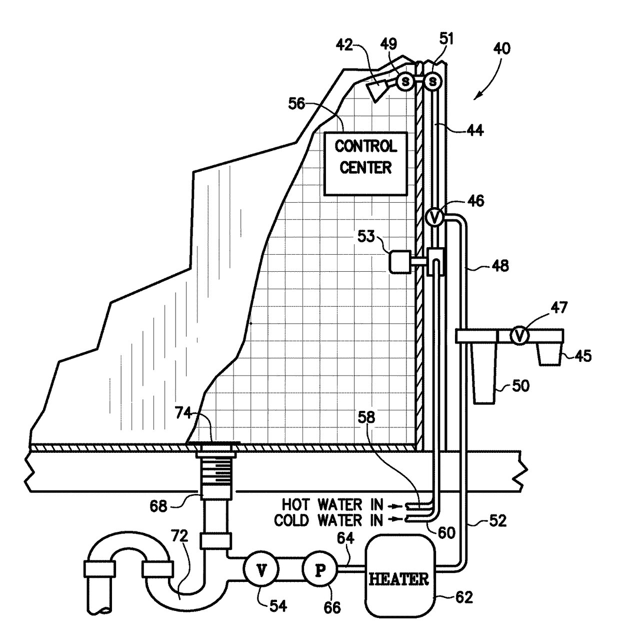
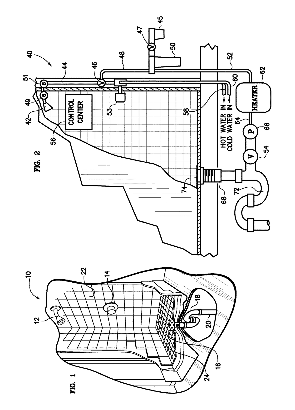
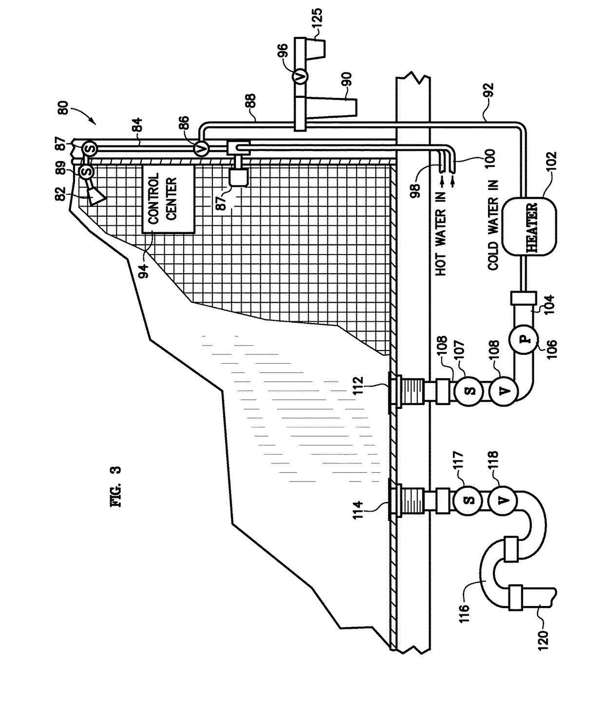
[0021]Referring now to the drawings and particularly to FIG. 1 is a perspective view of a typical shower enclosed in housing consisting of two to four walls 22 with a floor 24. Generally, at the lowest point and usual near the center or one edge is the drain 16 that is connection to a P tray 18 that connects to the sewer line 20. A water control valve 14, generally has a hot and cold (ambient) water supply lines in fluid connection and the valve 14 controls the water pressure and the ratio of hot and cold water to the shower. A general shower head 12 exits the wall where the control valve 14 is located. When one begins the shower, generally the control valve 14 is turn on and wasted water is allowed to flow down the drain 16, through the P trap 18, and down the sewer 20, until the water attains the desired temperature ranging in 90-100 degrees Fahrenheit. The duration of the shower is dependent on initial rinsing, body soap application, hair shampoo / conditioner application, various ...


PUM

PropertyMeasurementUnit
temperatureaaaaaaaaaa

Abstract

The present invention is a system that recycles shower water to promote water conservation. The system comprises a plurality water valves for opening and closing water lines, sensors for temperature and presence of soap / shampoo / conditioner in the water, a heater, a filter means, and a control center. This system has the capability to monitor when the water is clean and then channels water to be recycled and supplemented with heating, filtering, and a percentage of fresh hot and cold (ambient) water. The control center continuously monitors the water for cleanliness or contaminated with soap products and can switch between a recycle mode and a non-recycle mode. The temperature sensor monitors the recycle water temperature and activates a heater to increase the temperature if needed.

Description

FIELD OF THE INVENTION[0001]This apparatus relates to a water-recycling shower or bath and more particularly relates to a shower apparatus for the recirculation of water in homes, commercial facilities, exercise facilities and the like to effect a conservation of water wherein water, once used in the showering process, is recycled during a portion of the showering process in place of fresh water in order to effect a conservation of water which structure is especially useful under conditions of limited availability of water.BACKGROUND OF THE INVENTION[0002]In many parts of the United States and other countries throughout the world, there are either persistent or periodic draught conditions which may last for one or more years. As a result, water becomes a precious commodity. Various governmental institutions, as a matter of necessity, impose restrictions on the quantity of water which may be used. These restrictions generally apply to commercial institutions such as hotels and indust...

Claims


Application Information

Patent Timeline
Patent Type & Authority Applications(United States)
IPC IPC(8): E03C1/00A47K3/28C02F9/00B01D29/56B01D35/157
CPCE03C1/00C02F1/68B01D35/1573C02F9/00A47K3/28C02F2101/301C02F2101/308C02F2103/003C02F2209/11C02F2209/10C02F2209/02C02F2209/40C02F2101/36C02F2101/12C02F2303/20C02F1/008C02F1/50C02F1/32C02F1/001C02F1/66C02F1/283B01D29/56C02F1/722C02F1/76E03B7/04C02F2103/002C02F2209/005C02F2303/185E03C2201/40A47K3/281C02F9/20
Inventor KLICPERA, MICHAEL EDWARDBUTLER, ANN MARIE
Owner KLICPERA MICHAEL EDWARD
Learn More