This helps you quickly interpret patents by identifying the three key elements:
Problems solved by technology
Method used
Benefits of technology
[0012]The main objective of the present invention is to provid
Problems solved by technology
First, the welded steel bars of the conventional assembled house cannot be manufactured in the factory in advance, and must be welded on the site of the assembled house.
Thus, the constructing of the assembled house on the site thereof must take much time.
Second, the welded portions on the steel bars easily rust.
Third, if the welding work is not done properly, the connecting strength between the beam and the column may be not strong enough.
Fourth, after the
Method used
Image
Click on the blue label to locate the original text in one second.
Reading with bidirectional positioning of images and text.
Examples
first embodiment
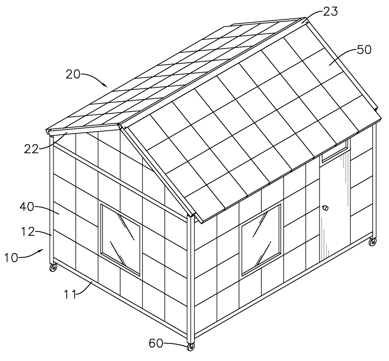
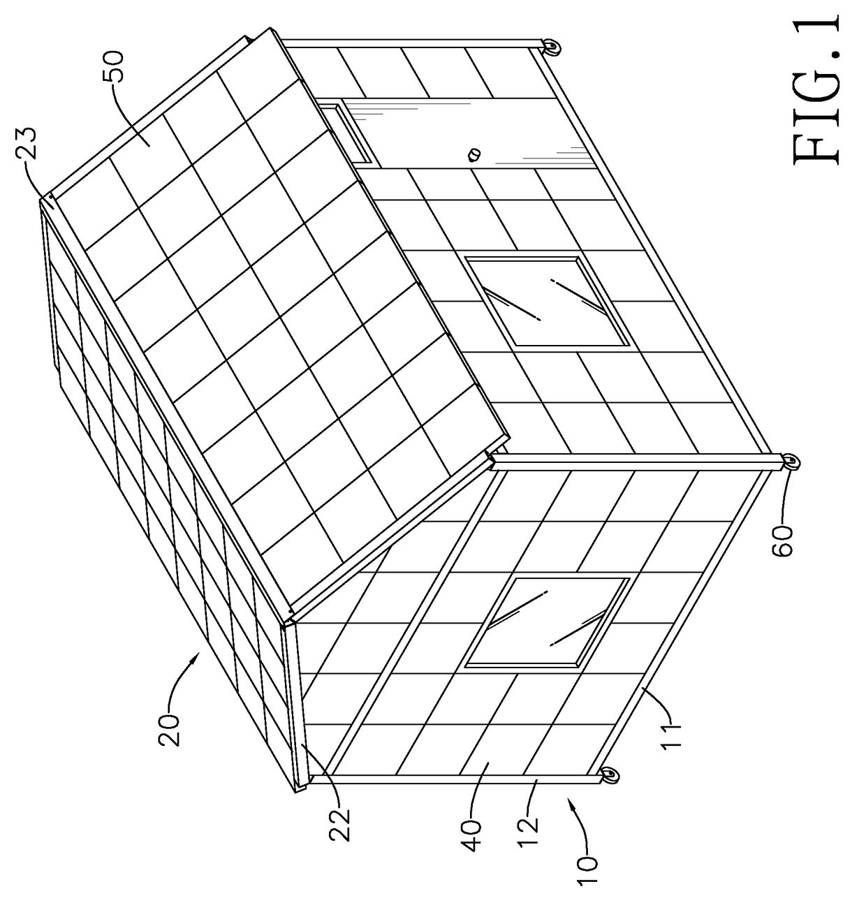
[0045]the present invention is a basic-type assembled house, which has a sloped roof.
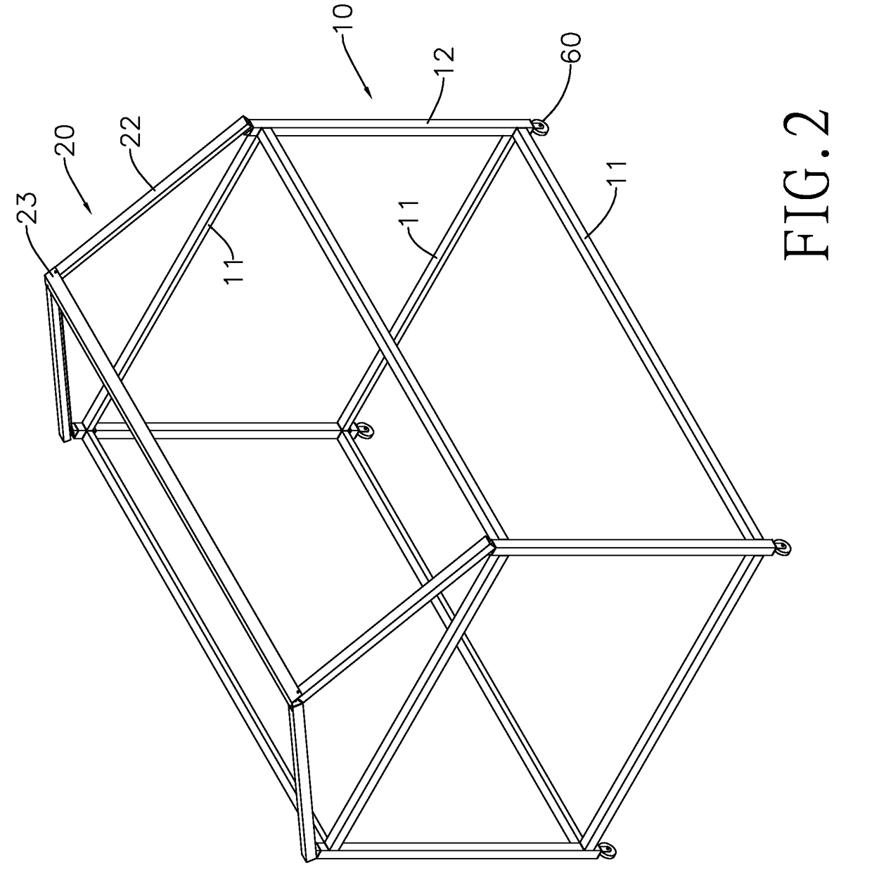
[0046]The house framework 10 has eight beams 11 arranged into two rectangular loops, four columns 12 mounted between said two rectangular loops, and eight connectors 13.
[0047]With reference to FIGS.3 to 6, each one of the beams 11 is a horizontally elongated and hollow square tube, and has four side walls 111, two end walls 112 and an elongated opening 113. The end panels 112 are connected to the four side walls 111. The elongated opening 113 is formed through one of the side walls 111 and extending to the two end walls 112.
[0048]Each one of the columns 12 is a vertically elongated and hollow square tube, and has four side walls 121. The column 12 has, but not limited to, two end openings 122.
[0049]The connectors 13 are mounted securely in the columns 12. Four of the eight connectors 13 are disposed near bottoms of the four columns 12 for respectively connecting four wheels 60. The other four connec...
third embodiment
[0064]With reference to FIG. 15, the present invention is similar to the first embodiment, but in the roof framework 20B, there are holes 231B between the beam cover 23B and the rafters 22B for air ventilation.
[0065]To sum up, the beams 11, the columns 12, the rafters 22, and the ridge beams 21 are connected to each other mainly by screwing the screws into the connectors 13 mounted inside of the columns 12, such that welding is not required when the house framework is assembled on the site of the assembled house, thereby effectively accelerating the assembling. In addition, the beams 11, the columns 12, the rafters 22, and the ridge beams 21 are connected without welding, which eliminates the problem that the welded portions may easily rust. Furthermore, the beams 11, the columns 12, 22, and the ridge beams 21 are all hollow tubes, which can effectively lower the weight of the whole assembled house.
PUM
Abstract
An assembled house has a house framework, a roof framework, wall panels and a roof panel. The house framework has multiple beams, columns, and connectors. The roof framework has multiple rafters. Each one of the connectors is mounted securely in the column, and has multiple screw sleeves mounted securely in a concrete body. Thus, the beam can be connected securely to the column by screws screwed into the screw sleeve of the connector. Welding is not required for assembling the house framework on the site of the assembled house, thereby effectively accelerating the assembling. In addition, the beams and the columns are connected without welding, which eliminates the problem that the welded portions may easily rust. Furthermore, the columns, rafters, and the beams are hollow tubes, which can effectively lower the weight of the whole assembled house.
Description
BACKGROUND OF THE INVENTION[0001]1. Field of the Invention[0002]The present invention relates to an assembled house, especially to an assembled house that can be assembled quickly and easily.[0003]2. Description of the Prior Arts[0004]Comparing with a traditional house that is constructed in reinforced concrete, an assembled house can be constructed quickly and has lower cost. Thus, the assembled houses are often used as temporary residences. A conventional assembled house has a house framework and multiple wall panels. The house framework is formed by welding multiple steel bars together. The wall panels are mounted between the steel bars to form walls, the floor, and the roof of the conventional assembled house.[0005]However, the conventional assembled house has three shortcomings[0006]First, the welded steel bars of the conventional assembled house cannot be manufactured in the factory in advance, and must be welded on the site of the assembled house. Thus, the constructing of th...
Claims
Application Information
Patent Timeline
Application Date:The date an application was filed.
Publication Date:The date a patent or application was officially published.
First Publication Date:The earliest publication date of a patent with the same application number.
Issue Date:Publication date of the patent grant document.
PCT Entry Date:The Entry date of PCT National Phase.
Estimated Expiry Date:The statutory expiry date of a patent right according to the Patent Law, and it is the longest term of protection that the patent right can achieve without the termination of the patent right due to other reasons(Term extension factor has been taken into account ).
Invalid Date:Actual expiry date is based on effective date or publication date of legal transaction data of invalid patent.