Steel stud anchor

a technology of steel studs and anchors, which is applied in the direction of screws, threaded fasteners, bolts, etc., can solve the problems of drywall anchors, steel stud construction is not without its problems, and is extremely difficult and time-consuming to fasten most things to walls, etc., and achieves the effect of easy removal and movemen

Active Publication Date: 2017-05-25
CALL FRLIN JIRI +1
View PDF3 Cites 1 Cited by
  • Summary
  • Abstract
  • Description
  • Claims
  • Application Information

AI Technical Summary

Benefits of technology

The present invention is a steel stud anchor that has a unique concave profile and an unusual auger-like thread style and progression that causes the steel stud to curl around the anchor and hold it fast. This results in a far superior grip. The threads on the shaft are resistant to stripping when threaded into a steel stud hole. The anchor can be directly fastened to a steel stud without the need for bulking up the wall with wood, and it can hold much greater weights in less time with less skill and hassle. The anchor can also be used as an anchor itself or in conjunction with other hooks, clips, hangers, and anything else desired to be screwed in to a wall. The void in the anchor allows for the insertion of caps or other anchors or fasteners. The helical thread winding around the anchor shaft translates the rotary motion applied to the fastener head by the drill into a linear translation of the anchor toward the steel stud supporting the wall substrate of wall cladding and millwork, piercing the steel stud and forming a rigid anchor.

Problems solved by technology

These solid wooden studs were sturdy and the process, although wasteful, allowed builders and homeowners alike to easily fasten millwork and other heavy objects to walls by using a wood screw to connect the millwork to the structural timber framing members of the home.
However, drywall anchors are generally load rated at only around 50 lbs.
Steel stud construction is not without its problems, however.
For example, the light gauge and weight of the steel studs has made it extremely difficult and time consuming to fasten most things to walls.
A typical interior partition framed with steel studs has a drywall face just like the wooden framed wall but the studs inside are hollow and quite flimsy.
Conventional wood or sheet metal screws were not designed for use with a thin, hollow steel stud because the steel stud offers little surface contact / contact substance for the screw threads to hold on to.
When coupled with the fact that the steel studs are quite malleable and easily distorted, the result is a poor match of fastener and framing member.
The wood and sheet metal screws stretch the hole they make in a steel stud and then can't be properly snugged up.
Further, the wood and sheet metal screws strip easily and they do not secure well to the sheet metal that is within a wall.
As a conventional metal or wood screw is tightened in a steel stud, it winds in adequately, but when an attempt is made to turn the thread a final time to secure the screw in the steel stud, the metal of the steel stud is displaced and the slender straight screw easily slips loose.
Drywall anchors designed for use in drywall, are no better in steel studs.
These screws are often too short to reach the steel stud behind the drywall.
When they can be threaded into a hole in a steel stud, they have similar issues as wood and sheet metal screws, such as tearing of the hole and stripping of the screw.
Further, drywall anchors are only rated for light weight applications.
To address the problem of fastening millwork to steel studs, builders have come up with a number of work-arounds, but these work-arounds have proven time consuming and costly, with none addressing the problem directly or effectively.
These alternatives are slow, time consuming, indirect and also quite pricey, not to mention inferior to simply screwing into wooden studs.
The threaded stud of the Lopez patent would not be suitable for fastening with a steel stud for the same reasons as a wood screw or sheet metal screw.
The thin steel stud would distort easily with the described threaded stud with the point of entry (pilot hole) being easily displaced, such that this fastener would lose its grip and not secure properly
Such a fastener is very specifically designed for mating concrete to metal and would not be appropriate for e.g. drywall as it would break apart the drywall and therefore would not tighten properly in a steel stud application.
Such a fastener would not be suitable for fastening with a steel stud for the same reasons as a wood screw or sheet metal screw.

Method used


Image

  • Steel stud anchor
  • Steel stud anchor
  • Steel stud anchor

Examples


Embodiment Construction

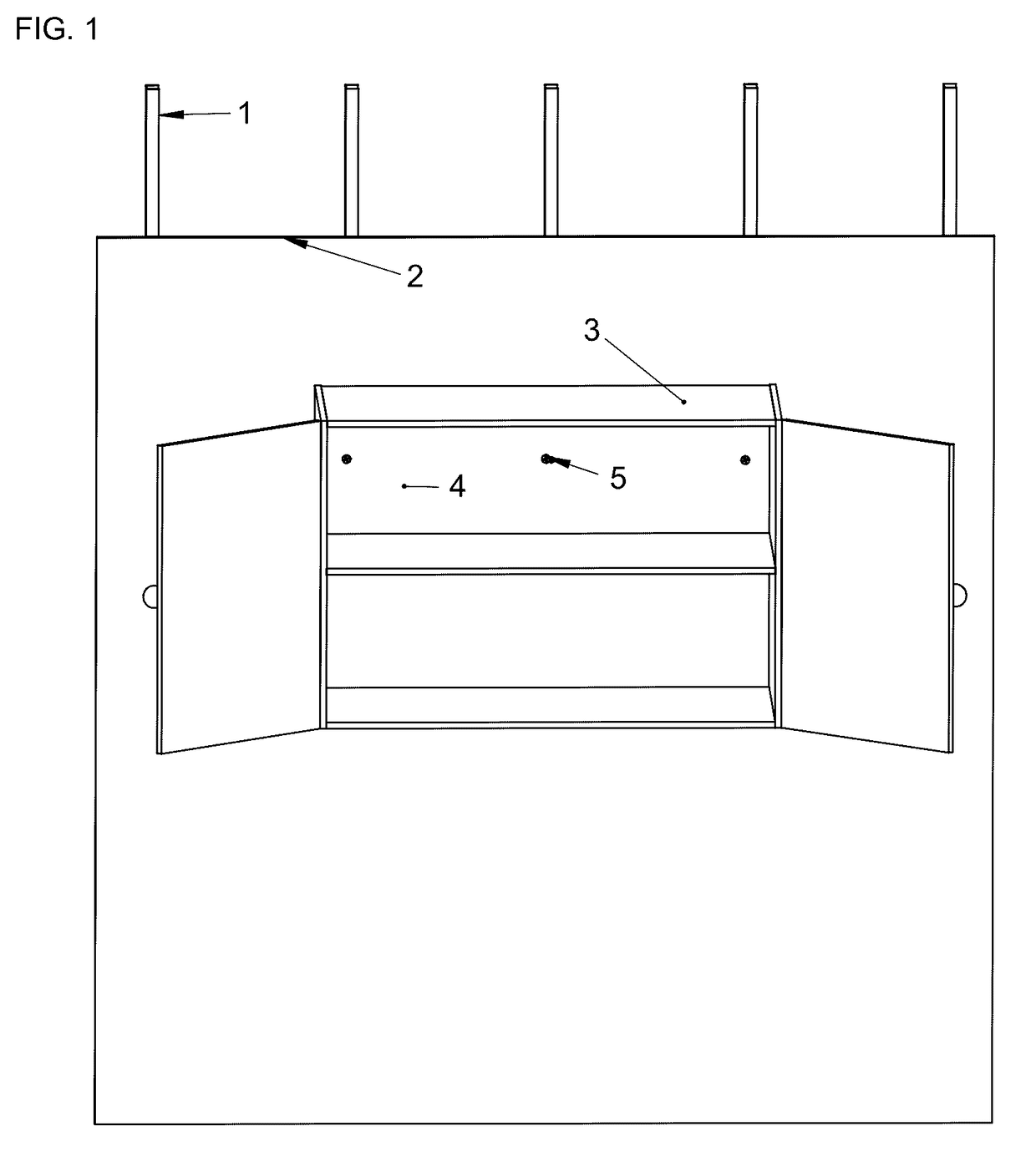
[0043]FIG. 1 shows a perspective isometric view of millwork 3 fastened to a steel stud wall, showing steel studs 1 vertically arranged in a generally regular spacing, and supporting wall cladding 2. Steel stud anchors 5 penetrate the back board 4 of the millwork 3, the rear plane of said backboard being contiguous with the generally vertical plane of the wall cladding 2. In this fashion, the millwork may bear a specific load, exemplified by a kitchen cabinet full of dishes. Other possible types of millwork include bookshelves, television mounts, audio equipment, artwork, mirrors, lighting, drapery, decorative millwork panels, handrails, conduit mounts and duct hangers. The load variable is a function of the wall material. The steel studs generally used in buildings for the erection of interior partitions can vary in thickness from about 0.0179″ (18 mils) or 0.455 mm (25 gauge) to about 0.0296″ (30 mils) or 0.752 mm (20 gauge) With thicker steel studs, the metal is heavier, sturdier ...


PUM


Abstract

A metal anchoring fastener fastens millwork onto walls constructed with wall cladding fastened to steel studs. The load typical of a loaded cabinet is borne by the steel stud anchors owing to the mate between the profile of the steel stud anchor and the layers of millwork and wall cladding and steel stud that said anchor penetrates. The pitch of the thread adorning the profile of the steel stud anchor progresses non-linearly along the length of said shaft, the shaft is generally non-linear in profile, and the thread profile is non-uniform along the length of said shaft. The anchor can also support a secondary screw concentrically penetrating the void at the center of the anchor, in order to hang loads from a wall, with or without millwork. Predrilling of the holes can enable installation of these zinc anchors.

Description

FIELD OF THE INVENTION[0001]This Invention relates generally to fasteners and more particularly to fasteners detailed to anchor in steel studs supporting walls in buildings.BACKGROUND OF THE INVENTION[0002]For generations, homes were framed with timber, with the interiors clad in drywall or some sort of wallboard. In a traditional wood-framed home, hanging things from the walls was neither difficult nor precarious. Mainly 2″×4″s and 2″×6″s were used. After the framing was finished, drywall or some wall board surface would be attached to the framing members, it would be painted and then the millwork would be attached, such as a kitchen cabinet, a bathroom vanity, book cases etc. These solid wooden studs were sturdy and the process, although wasteful, allowed builders and homeowners alike to easily fasten millwork and other heavy objects to walls by using a wood screw to connect the millwork to the structural timber framing members of the home. The solid wood stud provided plenty of s...

Claims


Application Information

Patent Timeline
Patent Type & Authority Applications(United States)
IPC IPC(8): F16B25/00E04B2/58E04F13/08F16B25/10
CPCF16B25/0021E04F13/0832E04B2/58F16B25/103F16B23/0007Y10T29/49963F16B25/10F16B25/0031F16B25/0073F16B25/0057F16B25/0078F16B25/0042F16B21/00F16B25/00
Inventor CALL, FRANKLIN JIRIROBBESON, MARK
Owner CALL FRLIN JIRI
Why Eureka
Try Eureka